
Pulse air injection nozzle with dual columnar slits and bag filter dust removal system using same

A technology for cleaning air and injection nozzles, applied in the field of cleaning systems, can solve the problems of reduced effect, difficulty in connecting the injection tube 405, and reduced suction effect of surrounding air, so as to reduce installation costs and maintenance costs, and improve cleaning efficiency

Active Publication Date: 2012-12-05
KOREA INST OF ENERGY RES
View PDF7 Cites 6 Cited by
  • Summary
  • Abstract
  • Description
  • Claims
  • Application Information

AI Technical Summary

Problems solved by technology

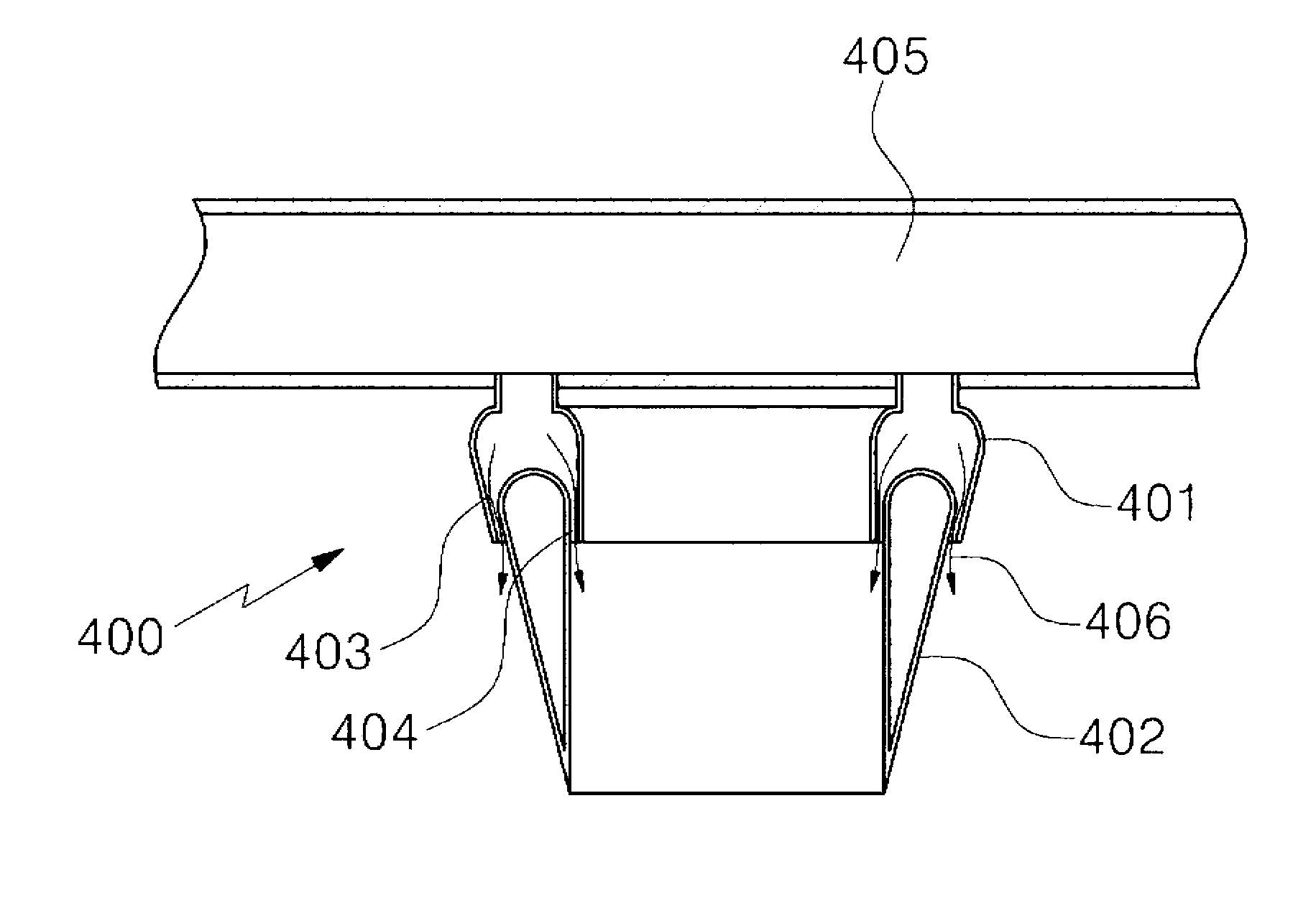
However, image 3 A disadvantage of the double annular groove nozzle shown in is that the effect of drawing air around the nozzle top into the nozzle is reduced because the injection through the inner groove 404 does not follow along the curved surface but is directed directly to the vertical underside, And the suction effect of the surrounding air is reduced, because the injection through the outer groove 404 is not carried out along the curved surface but along the vertical slope of the lower guide 402
A disadvantage of the double annular groove nozzle 400 is also that it has an external shape that is difficult to connect to the injection tube 405

Method used


Image

  • Pulse air injection nozzle with dual columnar slits and bag filter dust removal system using same
  • Pulse air injection nozzle with dual columnar slits and bag filter dust removal system using same
  • Pulse air injection nozzle with dual columnar slits and bag filter dust removal system using same

Examples


Embodiment Construction

[0068] Before describing various embodiments of the present invention in detail, it is to be understood that the present invention is not limited to the construction and arrangement of elements described in the following specification or illustrated in the accompanying drawings. The invention can be embodied in different embodiments and carried out in various ways. Terms denoting the orientation of a device or element (such as "front," "rear," "top," "bottom," "top," "bottom," "left," "right," and "landscape") are used to simplify this description of the invention, and neither represents nor implies that a device or element has a particular orientation. Terms such as "first" and "second" used in the specification or claims are not intended to represent or indicate relative importance or meaning.

[0069] The present invention has the following features to achieve the above objects.

[0070] Hereinafter, exemplary embodiments of the present invention will be described in deta...


PUM

PropertyMeasurementUnit
Inclinationaaaaaaaaaa

Abstract

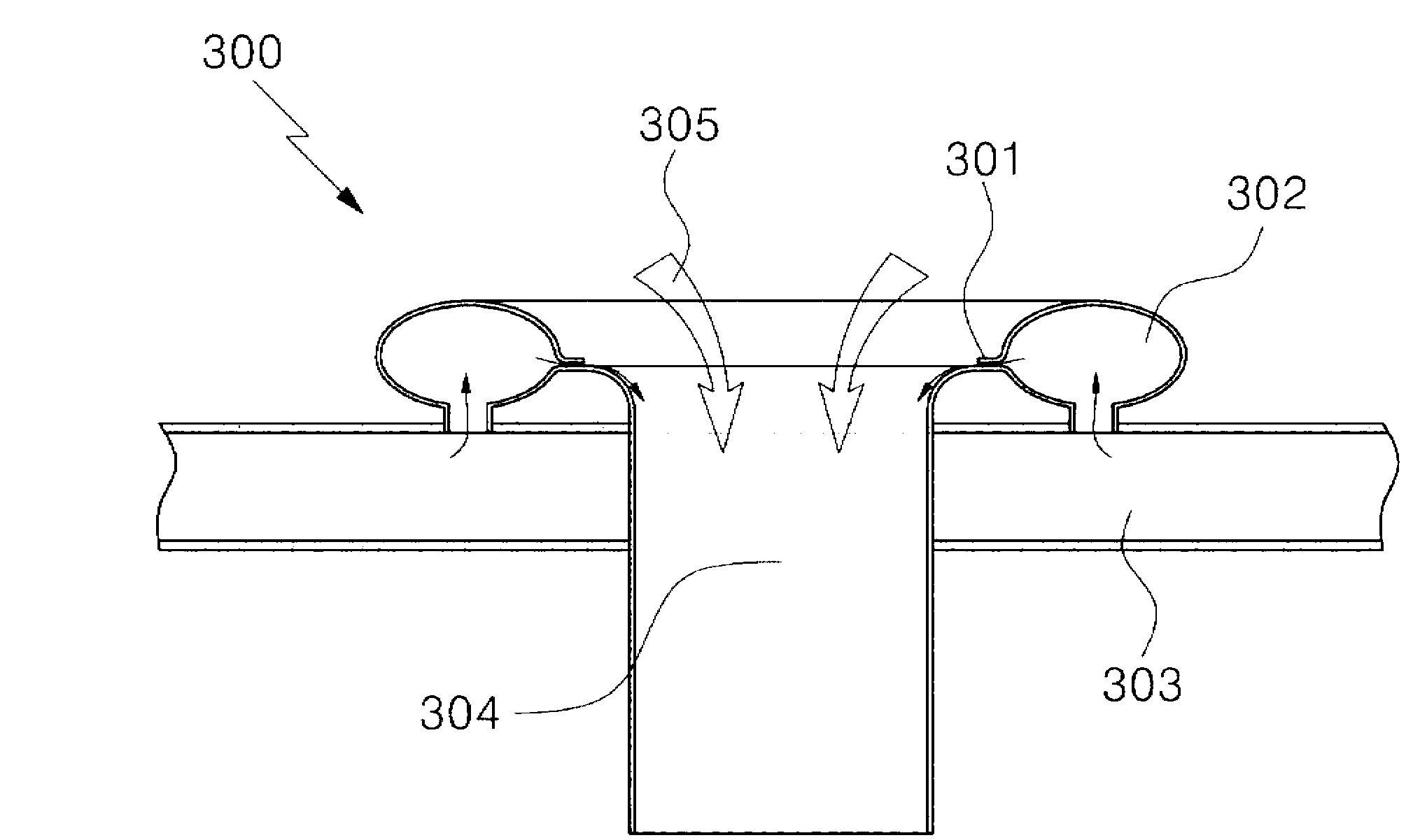
The present invention relates to a pulse air injection nozzle with dual columnar slits and a bag filter dust removal system using the same, in which the dust removal effect of a dust collector filter can be remarkably improved by introducing massive peripheral air with a small amount of compressed air, and more specifically, to a pulse air injection nozzle with dual columnar slits and a bag filter dust removal system using the same, wherein: internal horizontal columnar slits are formed inside in the upper part of an injection nozzle having an overall cylindrical shape,each of external vertical columnar slits is formed on the outer boundary of the injection nozzle,air currents injected from the internal horizontal columnar slits rapidly flow in a vertical downward direction along a curved surface whereby air pressure inside a cylinder is reduced to allow peripheral air in the upper part of the nozzle to flow into the inside of the nozzle quickly,and air currents injected from the external vertical columnar slits rapidly flow along a curved surface formed toward the inside of the cylindrical nozzle whereby air pressure around the outer side of the nozzle is reduced to allow the peripheral air to be enticed along the outer side of the nozzle, thereby increasing a flow of the overall pulse air introduced into the inside of the dust collector filter. Consequently, the invention is capable of highly improving the dust removal efficiency for removing dust attached to a surface of the dust collector filter.

Description

technical field [0001] The invention relates to a cleaning system for a filter dust collector corresponding to the dust collection technology in the technical field of air pollution control. Among various dust collection technologies such as electric dust collection technology, filter dust collection technology, centrifugal dust collection technology and dust washing and dust collection technology, the present invention belongs to the filter dust collection technology that uses a dust collection filter to remove dust contained in process gas . A dust collector that uses filter dust collection technology is called a filter dust collector. The filter dust collector includes a process gas inflow unit, a dust hopper, a dust removal transport and storage unit, a dust collection filter unit, a cleaning unit, a process gas discharge unit and a blower, wherein the present invention corresponds to the cleaning unit. Cleaning in filter dust collection technology means that the dust th...

Claims


Application Information

Patent Timeline
IPC IPC(8): B01D46/02B01D46/04B01D46/24B01D46/48
CPCB01D46/04B01D46/0068B01D46/71
Inventor 朴贤设林京洙
Owner KOREA INST OF ENERGY RES
Learn More