
Metamaterial antenna

A metamaterial and antenna technology, applied in the field of metamaterials, can solve the problems of small half-power bandwidth and small antenna half-power bandwidth, and achieve the effects of reducing half-power bandwidth, increasing the propagation distance, and increasing the front-to-back ratio.

Active Publication Date: 2014-12-24
KUANG CHI INST OF ADVANCED TECH +1
View PDF3 Cites 0 Cited by
  • Summary
  • Abstract
  • Description
  • Claims
  • Application Information

AI Technical Summary

Problems solved by technology

[0004] The purpose of the present invention is to solve the problem that the half-power bandwidth of the antenna in the prior art is small, and to provide a metamaterial antenna, which is provided with a metamaterial thin film layer at the front end of the antenna, so that the signal sent by the antenna has a Smaller half-power bandwidth to achieve long-distance signal transmission and reception

Method used


Image

  • Metamaterial antenna
  • Metamaterial antenna
  • Metamaterial antenna

Examples


Embodiment Construction

[0028] The present invention will be described in further detail below in conjunction with the embodiments and the accompanying drawings, but the embodiments of the present invention are not limited thereto.

[0029] Metamaterial is a new type of material with artificial microstructures as the basic unit, which is spatially arranged in a specific way and has special electromagnetic response, including periodically arranged artificial microstructures and substrates for artificial microstructures to attach to. The artificial microstructure is a planar structure or a three-dimensional structure that is composed of at least one metal wire and responds to electromagnetic waves. Multiple artificial microstructures are arranged in arrays on the substrate. The portion of each artificial microstructure and the substrate it is attached to is A metamaterial unit. The substrate can be any material different from the artificial microstructure. The superposition of these two materials produ...


PUM


Abstract

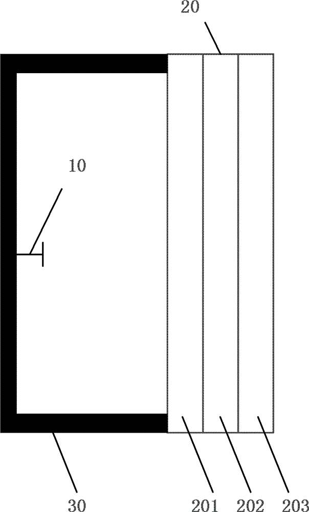
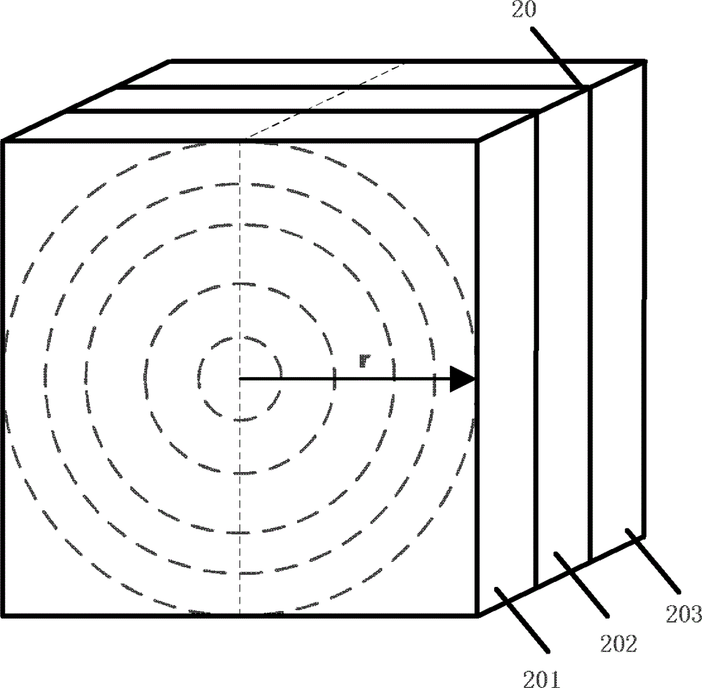
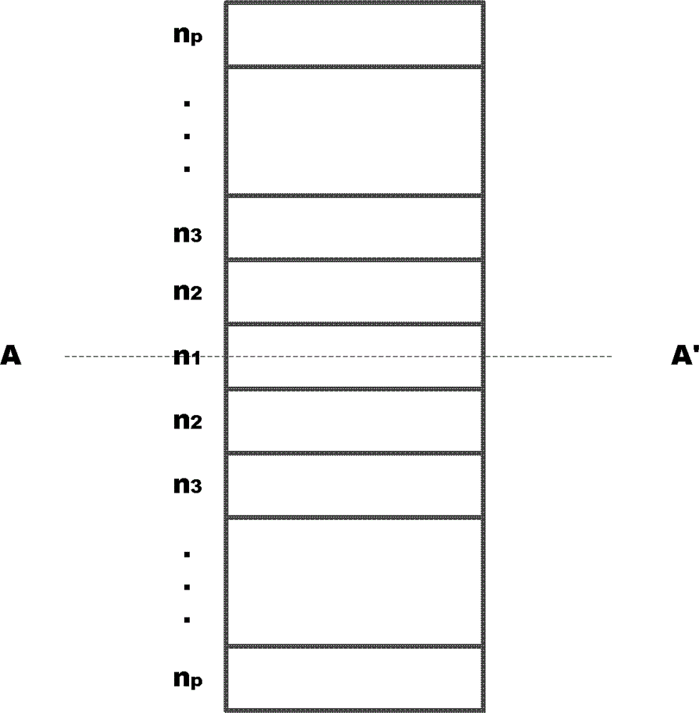
The invention relates to a metamaterial antenna, which comprises an oscillator, a metamaterial thin film layer, and a reflector, wherein the oscillator is positioned in the reflector and is used for generating electromagnetic waves; the metamaterial thin film layer consisting of a plurality of metamaterial sheet layers is used for converging the electromagnetic waves and radiating the electromagnetic waves outwards; and the reflector which is a cavity without cover is used for reflecting part of the electromagnetic waves generated by the oscillator to the metamaterial thin film layer, and the reflector and the metamaterial thin film layer form a sealed cavity. Half-power bandwidth of an antenna distant field is reduced by changing the refractive index distribution in the metamaterial thin film layer, so that transmission distance of the antenna is improved, and the front-to-back ratio of the antenna is increased at the same time.

Description

technical field [0001] The invention relates to the field of metamaterials, in particular to a metamaterial antenna. Background technique [0002] Half power angle, also known as 3dB beam width, half power beam width, half power bandwidth. In the power pattern diagram, in a certain plane containing the maximum radiation direction of the main lobe, the angle between two points where the relative maximum radiation direction power flux density drops to half (or less than the maximum value 3dB) is called half power beam width. In the field strength pattern, in a plane containing the maximum radiation direction of the main lobe, the included angle at which the field strength of the relative maximum radiation direction is reduced to 0.707 times is also called the half-power beam width. The horizontal half-power beamwidth refers to the half-power beamwidth of the horizontal pattern, and the vertical half-power beamwidth refers to the half-power beamwidth of the vertical pattern. ...

Claims


Application Information

Patent Timeline
Patent Type & Authority Patents(China)
IPC IPC(8): H01Q15/00H01Q15/02H01Q19/06H01Q19/10
Inventor 刘若鹏季春霖岳玉涛李云龙
Owner KUANG CHI INST OF ADVANCED TECH
Learn More