Method and device for testing fatigue of car thrust rod component

A fatigue test and test device technology, applied in the field of verifying its fatigue performance, can solve the problem of not involving the loading fatigue test of thrust rod components, etc.

Active Publication Date: 2012-11-28
ZHUZHOU TIMES NEW MATERIALS TECH
View PDF6 Cites 6 Cited by
  • Summary
  • Abstract
  • Description
  • Claims
  • Application Information

AI Technical Summary

Problems solved by technology

[0008] However, neither of the above two patents involves the multi-directional loading fatigue test of the thrust rod assembly, so it is necessary to improve this

Method used


Image

  • Method and device for testing fatigue of car thrust rod component
  • Method and device for testing fatigue of car thrust rod component
  • Method and device for testing fatigue of car thrust rod component

Examples


Embodiment 1

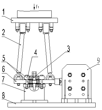
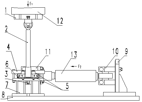
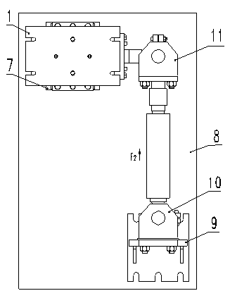
[0029]A fatigue test device for an automobile thrust rod assembly, comprising an upper test platform 1, the thrust rod assemblies 2 to be tested are installed in pairs, respectively connected to the upper test platform 1 through front-end ball joints, and a vertical actuator 12 passes through the upper test platform 1 Apply longitudinal tensile and compressive loads to the thrust rod assembly 2; it includes a rotary table 6, and the upper and lower sides of the rotary table 6 are provided with circular grooves, and polyethylene discs 5 or other smooth and wear-resistant materials are placed in the grooves, which are respectively connected with the upper and lower wear-resistant materials. The grinding plate 4 is in contact with the wear-resistant base 7, and the rear end ball joints of the thrust rod assembly 2 to be tested are respectively fixed on both sides of the rotary table 6; a lower test platform 8 is included, and the wear-resistant base 7 is fixed on the lower test pla...


PUM


Abstract

The invention discloses a method and device for testing fatigue of a car thrust rod component. The method for testing fatigue of the car thrust rod component comprises the steps of: mounting two to-be-tested thrust rod components in a test device in pairs, wherein the two to-be-tested thrust rod components are respectively connected with an upper test platform on the test device through a front-end spherical hinge and are fixed with a turntable of the test device through a back-end spherical hinge; mounting the turntable on a lower test platform to enable the turntable to rotate around the axis per se on the lower test platform; connecting the side surfaces of the turntable with a transverse actuator and providing a functional torque enabling the turntable to rotate by the transverse actuator; mounting a vertical actuator on the upper test platform and providing a lengthways tension and compression force by the vertical actuator; applying lengthways tension and compression loads to the thrust rod through the upper test platform by the vertical actuator and meanwhile fixing the transverse actuator on a horizontal base through a tail joint, connecting the transverse actuator with the turntable through an end-part joint, and applying offset and reciprocated torque to the thrust rod component to realize the fatigue test on the thrust rod component.

Description

technical field [0001] The present invention relates to a detection method and device, in particular to a fatigue test method and device for an automobile thrust rod assembly, in particular to a method for verifying its Methods and apparatus for fatigue performance. The invention belongs to the technical field of test methods and devices. Background technique [0002] The thrust rod is widely used in the non-independent suspension of trucks or passenger cars, connecting the frame and axle, [0003] In addition to the positioning function, it mainly transmits traction force, braking force and lateral reaction moment to ensure the driving safety and stability of the vehicle. Due to the complex fatigue conditions of the thrust rod, failure of the thrust rod ball joint, rod body or ball retaining ring may occur during actual operation, which will affect the safety and stability of the vehicle. Therefore, the thrust rod assembly is formally installed. Before starting the vehic...

Claims


Application Information

Patent Timeline
IPC IPC(8): G01M13/00
Inventor 李心王永冠王进林达文姜其斌张志强吴兴磊陈刚黄涛
Owner ZHUZHOU TIMES NEW MATERIALS TECH
Why Eureka
Try Eureka