
Micro unmanned aerial vehicle carbon fiber rotor wing and preparation method thereof

A carbon fiber, micro-miniature technology, applied in the field of micro-miniature UAV carbon fiber rotor and its preparation, can solve the problems of high mass, low output power, low lift, etc., and achieve the effects of low rotational speed, low power consumption, and improved efficiency

Active Publication Date: 2012-11-28
BEIJING SATELLITE MFG FACTORY
View PDF5 Cites 18 Cited by
  • Summary
  • Abstract
  • Description
  • Claims
  • Application Information

AI Technical Summary

Problems solved by technology

However, the rotors of domestic micro-miniature UAVs use plastic rotors used in model aircraft. Plastic rotors are selected for their large mass and low lift; under the unit power consumption, the output power is small, which cannot meet the requirements of long-range and high-altitude conditions. flight requirements

Method used


Image

  • Micro unmanned aerial vehicle carbon fiber rotor wing and preparation method thereof
  • Micro unmanned aerial vehicle carbon fiber rotor wing and preparation method thereof
  • Micro unmanned aerial vehicle carbon fiber rotor wing and preparation method thereof

Examples


Embodiment

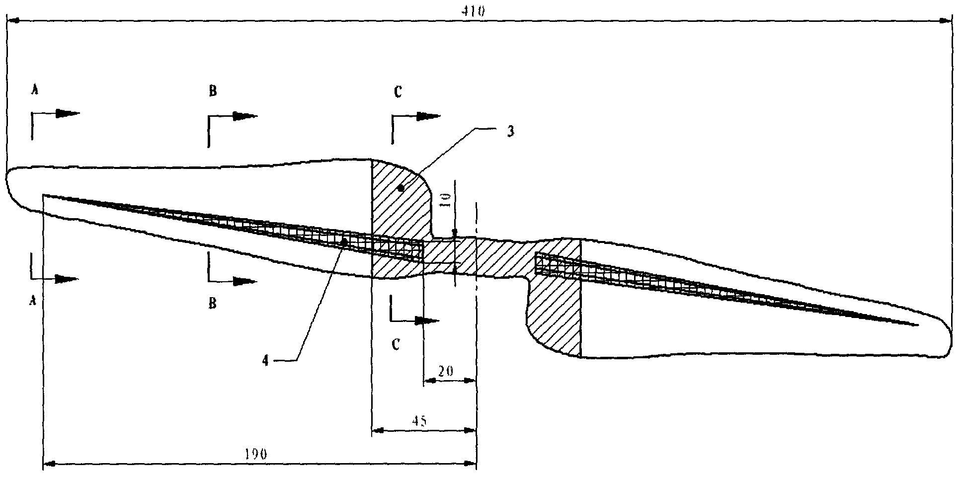
[0041] A carbon fiber rotor for micro-miniature drones, such as figure 1 As shown; the rotor from both ends to the middle is the wingtip, wing body and wing root in turn; the total length of the rotor is 410mm, counting from the center of the rotor as the origin, the left side of the origin is negative, and the right side of the origin The side is positive, from -45 to +45 is the wing root, from -190 to -45 and +45 to +190 is the wing body, and the rest is the wing tip;

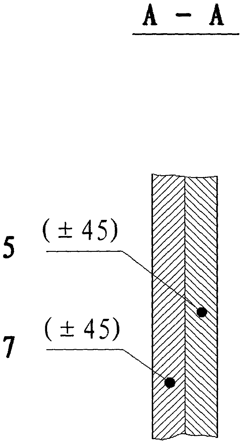
[0042] Wing tip is successively upper surface layer 5 and lower surface layer 7 from top to bottom; figure 2 shown;

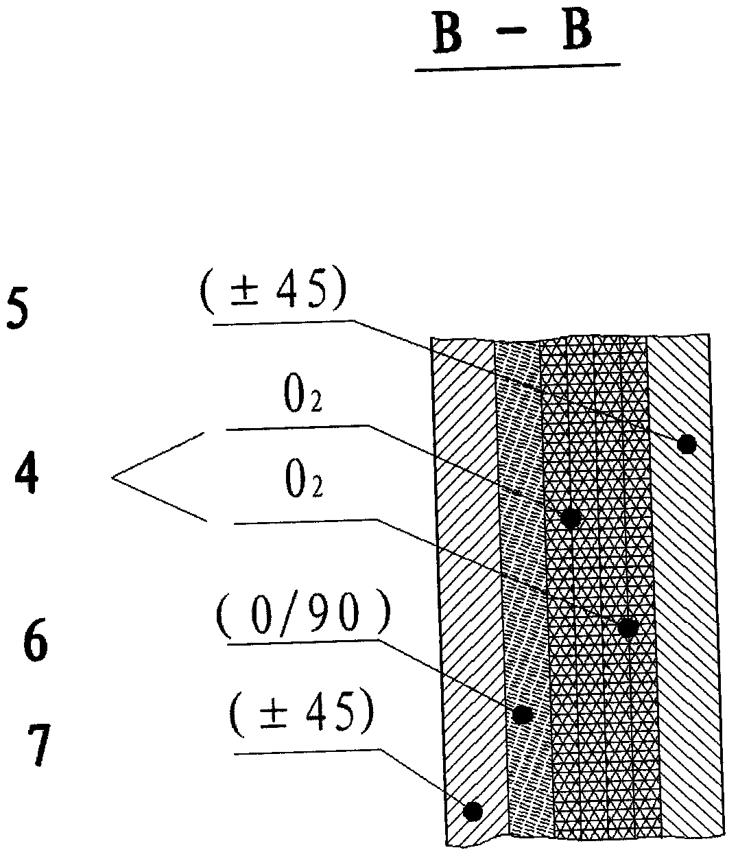
[0043] From top to bottom, the wing body is the upper surface layer 5, the ribs 4, the middle layer 6 and the lower surface layer 7; image 3 shown;

[0044] From top to bottom, the wing root is the upper surface layer 5, the rib 4, the reinforcement layer 3, the middle layer 6 and the lower surface layer 7; Figure 4 shown;

[0045] Above-mentioned upper surface layer 5 adopts 45 ° of c...


PUM

PropertyMeasurementUnit
Thicknessaaaaaaaaaa

Abstract

The invention relates to a micro unmanned aerial vehicle carbon fiber rotor wing and a preparation method thereof, belonging to the technical field of composite material structures. The rotor wing sequentially comprises a wing tip, a wing body and a wing root from two ends to middle; the wing tip sequentially comprises an upper surface layer and a lower surface layer from top to bottom; the wing body sequentially comprises an upper surface layer, a reinforcing rib, a middle layer and a lower surface layer from top to bottom; the wing root sequentially comprises an upper surface layer, a reinforcing rib, a reinforcing layer, a middle layer and a lower surface layer from top to bottom; and each reinforcing rib extends from the wing root to the critical part of the wing body and the wing tip and is narrowed gradually. Compared with a domestic plastic rotor wing with the same specification, the weight of the rotor wing provided by the invention is reduced by 65%; under unit mass, the output power of the rotor wing provided by the invention is 3.4 times that of the plastic rotor wing; under unit power consumption, the output power of the rotor wing provided by the invention is 1.3 times that of the plastic rotor wing; and under the condition of generating the same lifting power, the power consumption of the rotor wing provided by the invention is reduced by 40%, and the rotation speed is reduced by 30%. The rotor wing provided by the invention can improve the lift efficiency of an unmanned aerial vehicle under the conditions of low rotation speed and low power consumption.

Description

technical field [0001] The invention relates to a carbon fiber rotor for a miniature unmanned aerial vehicle and a preparation method thereof, belonging to the technical field of composite material structures. Background technique [0002] People usually refer to drones with a wingspan / length of less than 2m and a mass of less than 50kg as small drones, and drones with a wingspan / length of less than 30cm and a mass of less than 1kg are called micro drones. [0003] In countries with developed helicopter technology, unmanned helicopters have been developed very early. Unmanned aerial vehicle (UAV) has all kinds of combat functions required by the general battlefield. It can conduct reconnaissance, surveillance, air patrol, and indicate targets to other combat weapons. It can also participate in electronic warfare, a ubiquitous confrontation activity on the future battlefield. [0004] Compared with the foresight of developed countries in the field of UAV research, my country...

Claims


Application Information

Patent Timeline
IPC IPC(8): B64C27/46B29C70/34B29C33/00B29C33/30B29C35/02
Inventor 马立王存斌李昊李昞辉白忠奕白越
Owner BEIJING SATELLITE MFG FACTORY
Learn More