
Device for measuring material refractive index temperature coefficient under low temperature based on minimum deviation angle method

A technology of minimum deflection angle method and refractive index temperature, which is applied in the measurement of phase influence characteristics, etc., can solve the problems of error sensitivity, total reflection, measurement failure, etc., and achieve the effect of improving measurement accuracy, simple components, and avoiding failure to work.

Inactive Publication Date: 2012-11-21
INST OF OPTICS & ELECTRONICS - CHINESE ACAD OF SCI
View PDF3 Cites 17 Cited by
  • Summary
  • Abstract
  • Description
  • Claims
  • Application Information

AI Technical Summary

Problems solved by technology

Refractive index measurement accuracy10 -5 , but it can only measure the low-temperature refractive index (0.4-1.7μm) from visible light to near-infrared, the temperature control range of the sample is 100~300K, and the system uses the vertical incidence method, which is sensitive to errors and only suitable for measuring refraction Samples with a lower refractive index are prone to total reflection when measuring samples with a higher refractive index, resulting in measurement failure
At present, there is no relevant report on the refractive index data of infrared materials at low temperature (below 120K) and the refractive index measurement equipment of infrared materials at low temperature in China. Therefore, the accurate measurement of the refractive index of infrared materials at low temperature is of great significance to the development of low temperature optics.

Method used


Image

  • Device for measuring material refractive index temperature coefficient under low temperature based on minimum deviation angle method
  • Device for measuring material refractive index temperature coefficient under low temperature based on minimum deviation angle method
  • Device for measuring material refractive index temperature coefficient under low temperature based on minimum deviation angle method

Examples


Embodiment Construction

[0024] The present invention will be described in detail below with reference to the drawings and specific embodiments.

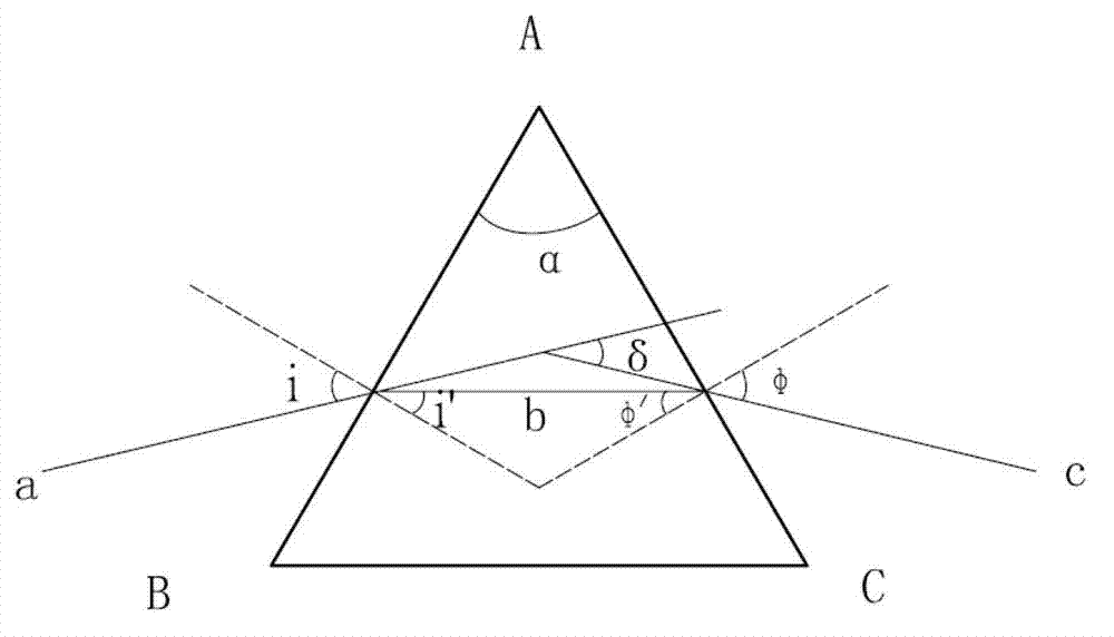
[0025] A device for measuring the temperature coefficient of the refractive index of a material at low temperatures. Its principle is the minimum deflection angle method. The minimum deflection angle method to determine the refractive index of materials technology, figure 1 It is shown as the working principle diagram. When the light is incident on the AB surface of the prism at the incident angle i and then successively refracted by the two optical surfaces AB and AC of the prism, The angle shoots from the AC side. The angle δ between the outgoing light and the incident light is called the deflection angle. For a given prism, the value of the deflection angle δ varies with the incident angle i. When the incident angle i is equal to the exit angle φ, the deflection angle δ will reach the minimum value δ 0 ,δ 0 It is called the minimum deflection angle. Accor...


PUM


Abstract

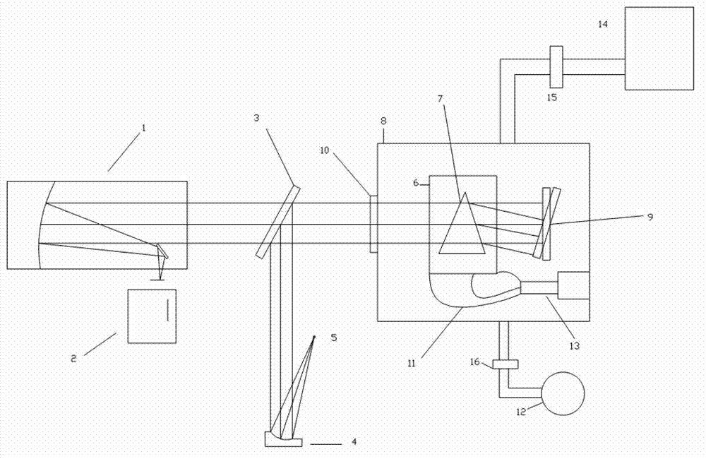
The invention provides a device for a measuring material refractive index temperature coefficient under low temperature based on a minimum deviation angle method. The device comprises a collimation light source system, a spectroscope, a collimation system, a low-temperature vacuum bin, a low-temperature vacuum system, a sample bin, a rotary reflection mirror, an electrically-controlled rotary table and an encoder. The low-temperature vacuum system, the sample bin, the rotary reflection mirror, the electrically-controlled rotary table and the encoder are subsidiary to the low-temperature vacuum bin. The sample bin and the rotary reflection mirror are driven by a motor respectively and are disposed in the low-temperature vacuum bin. When the device is used for measuring, quasi-monchromatic parallel light beams are emitted from a collimation light source and are emitted into the low-temperature vacuum bin after refection by the spectroscope, placement angles of reflection mirrors on a triple prism and the encoder are rotated to be adjusted to figure out a position of a minimum deviation angle, the light beams are perpendicularly emitted into the rotary reflection mirror, finally return to the spectroscope and enter the collimation system after being reflected. The traditional minimum deviation angle method is modified, the auto-collimation principle and the minimum deviation angle method are combined, demands for high precision of a shaft encoder are lowered within equal measuring precision ranges, and accordingly systematic cost is reduced.

Description

Technical field [0001] The invention belongs to the technical field of optical precision measurement, and in particular relates to a device for measuring the temperature coefficient of the refractive index of materials at low temperatures based on the minimum deflection angle method. The device is a device for measuring the refractive index of infrared or visible light materials under low temperature conditions. Background technique [0002] The development of low-temperature optical technology provides an excellent way for infrared observation. In China, due to the lack of data on the refractive index value of infrared transmission materials at low temperature and the rate of change of refractive index with temperature, only a total reflection low-temperature optical system can be developed at present. Therefore, one of the keys to successfully developing a refractory low-temperature optical system is to have the refractive index data of infrared materials at low temperatures. I...

Claims


Application Information

Patent Timeline
Patent Type & Authority Applications(China)
IPC IPC(8): G01N21/41
Inventor 倪磊廖胜任栖峰段沽坪
Owner INST OF OPTICS & ELECTRONICS - CHINESE ACAD OF SCI
Learn More