Measurement device and method for material refractive index and refractive index temperature coefficient

A technology of refractive index temperature and measuring device, which is applied in the direction of analyzing materials, measuring phase influence characteristics, instruments, etc., can solve problems such as error sensitivity, measurement failure, total reflection, etc., and achieve the goals of improving measurement accuracy, simple components, and reducing equipment cost Effect

Inactive Publication Date: 2017-05-31
SOUTHWEAT UNIV OF SCI & TECH
View PDF5 Cites 2 Cited by
  • Summary
  • Abstract
  • Description
  • Claims
  • Application Information

AI Technical Summary

Problems solved by technology

Refractive index measurement accuracy10 -5 , but can only measure the low-temperature refractive index (0.4-1.7μm) from visible light to near-infrared, the temperature control range of the sample is 100-300K, and the system uses the vertical incidence method, which is sensitive to errors and is only suitable for measuring refraction Samples with a lower refractive index are prone to total reflection when measuring samples with a higher refractive index, resulting in measurement failure
At present, there are no relevant reports on the refractive index data of infrared materials at low temperature (below 120K) and the refractive index measurement equipment of infrared materials at low temperature in China. Therefore, accurate measurement of the refractive index of infrared materials at low temperature is of great significance to the development of low temperature optics.

Method used


Image

  • Measurement device and method for material refractive index and refractive index temperature coefficient
  • Measurement device and method for material refractive index and refractive index temperature coefficient
  • Measurement device and method for material refractive index and refractive index temperature coefficient

Examples


Embodiment Construction

[0023] The technical solution of the present invention will be further described in detail below in conjunction with the accompanying drawings and specific embodiments.

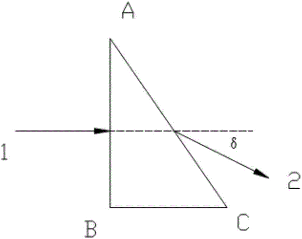
[0024] The principle of the invention is the vertical incidence method, which measures the refractive index of materials, has simple principle, convenient operation, and is more suitable for measuring the low temperature refractive index. Its measurement principle is as figure 1 , ABC is the sample prism made of the sample to be tested. The incident ray 1 is vertically incident on the sample prism ABC from the AB surface. According to the law of refraction, it propagates in the sample prism without deflection. The outgoing ray 2 is deflected by the AC surface, and the deviation angle is δ, from the properties of geometrical optics, it can be concluded that the refractive index The relationship between the refractive index n' and the change Δδ of the deflection angle after the sample temperature is changed i...


PUM


Abstract

The invention discloses a measurement device and method for the material refractive index and the refractive index temperature coefficient. The device comprises a collimation light source system, an aiming system, a low-temperature vacuum chamber, a sample chamber, a two-sided rotating reflector, an electronically controlled rotary table and an autocollimator. When the temperature in the sample chamber changes, the refractive index of a sample will accordingly change, the deviation angle will change slightly, the deviation angle variation can be measured through the autocollimator, and then the refractive index change of materials at low temperature is obtained. The device and method are based on an improved vertical incidence method, the principle is simple, operation is convenient, the measured sample prism can be made of an infrared material or a visible light wave band material, and the application range is wide; compared with an exiting auto-collimation scheme, attenuation of a light beam is reduced, the detection efficiency is improved, and meanwhile the device cost is lowered, and the deviation angle measurement precision is improved.

Description

technical field [0001] The invention belongs to the technical field of optical precision measurement, and relates to a measuring device and method for the refractive index of a material and the temperature coefficient of the refractive index. Apparatus and method for determining coefficients. Background technique [0002] The development of low-temperature optical technology provides an excellent observation method for infrared observation. In China, due to the lack of data on the refractive index value of infrared-transmitting materials at low temperatures and the rate of change of refractive index with temperature, currently only total reflection low-temperature optical systems can be developed. Therefore, one of the keys to successfully develop a catadioptric low-temperature optical system is to have the refractive index data of infrared materials at low temperature. In foreign countries, there have been reports on the successful determination of low-temperature refracti...

Claims


Application Information

Patent Timeline
IPC IPC(8): G01N21/41
CPCG01N21/41G01N2201/0633G01N2201/102
Inventor 倪磊向北平石磊莫才友杨应洪
Owner SOUTHWEAT UNIV OF SCI & TECH
Why Eureka
Try Eureka