Part installing system

A technology of parts installation and parts, applied in the field of parts installation system, can solve problems such as low productivity

Active Publication Date: 2012-11-14
FUJI KK
View PDF4 Cites 2 Cited by
  • Summary
  • Abstract
  • Description
  • Claims
  • Application Information

AI Technical Summary

Problems solved by technology

[0009] Therefore, the problem to be solved by the present invention is to effectively solve the problem of low productivity caused by a part mounting machine stopping due to an error.

Method used


Image

  • Part installing system
  • Part installing system
  • Part installing system

Examples


Embodiment Construction

[0025] Hereinafter, an example embodying a mode for implementing the present invention will be described.

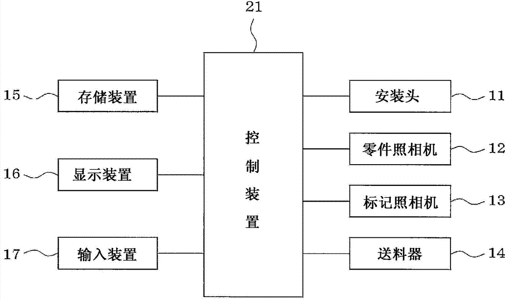
[0026] Such as figure 1 As shown, the parts mounting machine is provided with: a mounting head 11 holding one or more suction nozzles (not shown); a parts camera 12 that photographs parts sucked to the suction nozzles; and a reference position mark on the surface of the circuit board The marking camera 13; the feeder 14 for supplying parts; storing the later described image 3 A storage device 15 (storage unit) for various data such as various programs such as recovery installation programs, image processing data, etc.; a display device 16 such as a liquid crystal display, a CRT, etc.; an input device 17 such as a keyboard and a mouse.

[0027] The control device 21 of the parts mounting machine sucks the parts supplied from the feeder 14 through the suction nozzle of the mounting head 11, photographs the parts with the parts camera 12, and compares the part image with the im...


PUM


Abstract

The invention refers to a part installing system which can solve the problems of low productivity caused by stop of a part installing machine caused by error. If no errors occur when the part installing machine executes productive task of installing 1-n parts as shown in picture a, n parts of 1-n are installed in order as shown in picture b; when data errors need to be corrected in a process of installing a kth part, a warning message for promoting correcting data relative to the part k is displayed in a display, and meanwhile the installation of the part k is omitted and the installation of k+1,k+2,...n are continued. Wherein, if an operator corrects data relative to the part k as reason of causing errors, the recovery installation of the part k skipped by the error is executed when a last part n is installed.

Description

Technical field [0001] The invention relates to a parts mounting system, which sucks and mounts parts supplied through a feeder on a circuit board through an adsorption nozzle of a part mounting machine. Background technique [0002] Generally, in a part mounting system, as described in Patent Document 1 (JP 2008-218706 A), the part sucked to the suction nozzle is photographed by a camera, and the part image is combined with a pre-made image for processing The data is compared to judge the qualified / non-conforming parts of the parts. [0003] Theoretically, the image processing data can be used forever if it is generated once, but in reality, if the production lot or place of production of the image processing target part changes, the shape and size of the image processing target part need to be slightly changed. Correct the data for image processing. In addition, due to variations in the performance of the cameras used, variations in lighting conditions, etc., even the same part...

Claims


Application Information

Patent Timeline
Patent Type & Authority Applications(China)
IPC IPC(8): H05K13/04
Inventor 江崎弘健杉山健二三治满
Owner FUJI KK
Why Eureka
Try Eureka