Optical-fiber side surface coupled laser diode pumped solid-state laser and manufacture technology

A technology of laser diodes and solid-state lasers, which is applied to lasers, laser components, phonon exciters, etc., can solve the problems of difficult coupling adjustment, reduced coupling efficiency, and limited flexible coupling connections of lasers, so as to improve beam quality and simplify The effect of the output coupling structure

Inactive Publication Date: 2012-11-14
XIDIAN UNIV
View PDF6 Cites 2 Cited by
  • Summary
  • Abstract
  • Description
  • Claims
  • Application Information

AI Technical Summary

Problems solved by technology

[0002] Laser diode-pumped solid-state lasers (DPL) usually output directly in the form of a window. In the process of using DPL, the beam is directly output, which limits the flexibility of laser use and the relationship between the laser and other equipment using DPL. Coupling connection between
[0003] The traditional DPL fiber coupling output method is to add a coupling device outside the DPL output mirror (or laser housing), couple the beam output through the window into the optical fiber, and then pass through the optical fiber and other optical instruments (or equipment) using DPL. It is difficult to adjust the coupling by this method, and the coupling efficiency is likely to decrease after long-term use, and the coupling needs to be re-adjusted. At the same time, the size, weight and appearance of the DPL are increased.

Method used


Image

  • Optical-fiber side surface coupled laser diode pumped solid-state laser and manufacture technology
  • Optical-fiber side surface coupled laser diode pumped solid-state laser and manufacture technology
  • Optical-fiber side surface coupled laser diode pumped solid-state laser and manufacture technology

Examples


Embodiment 1

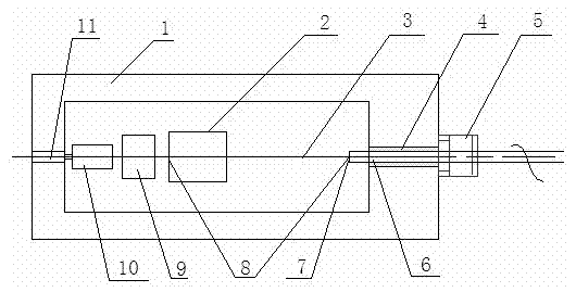
[0038] Such as figure 1 As shown, a fiber side-coupled laser diode-pumped solid-state laser includes a laser medium 2 and an output optical fiber 6 fixed in a housing 1, and the left end surface of the laser medium 2 is coated with a 1064nm full-reflection film and an 808nm full-transmission film. The right end face is coated with 1064nm anti-reflection film and 808nm total reflection film; the end face of output fiber 6 in housing 1 is coated with 1064nm partial transmission film and 808nm total reflection film, and the end face of laser medium 2 is coated with 1064nm total reflection film and output fiber 6 is coated with The end face with 1064nm partial transmission film forms a resonant cavity 8 in the housing 1, the end face laser diode 10 and the coupling lens 9 are fixed on the left end of the laser medium 2 from left to right, and the end face laser diode 10 acts on the laser medium through the coupling lens 9 2, the laser medium 2 is pumped outside the cavity by the e...

Embodiment 2

[0044] Such as Figure 4 As shown, the difference between embodiment 2 and embodiment 1 is that a Q-switched crystal 12 is added between the laser medium 2 and the inner end face of the output fiber 6 to form a laser diode-pumped Q-switched solid-state laser.

Embodiment 3

[0046] Such as Figure 5 As shown, the difference between Embodiment 3 and Embodiment 2 lies in that: not only a Q-switched crystal 12 is added between the laser medium 2 and the inner end face of the output fiber 6 to form a laser diode-pumped Q-switched solid-state laser. At the same time, a pumping side laser diode 14 is added on the side of the laser medium 2, and the pumping side laser diode 14 and the pumping end face laser diode 10 jointly pump the laser medium 2 to increase the output power.


PUM


Abstract

The invention relates to an optical-fiber side surface coupled laser diode pumped solid-state laser and a manufacture technology. The laser is characterized by comprising a laser medium and an output optical fiber, wherein the laser medium and the output optical fiber are fixed in a shell; one end surface of the laser medium is plated with a 1064nm total-reflection film and a 808nm total-penetration film; the end surface of the output optical fiber in the shell is plated with a 1064nm partial-penetration film and a 808nm total-reflection film; the end surface of the laser medium, which is plated with the 1064nm total-reflection film, and the end surface of the output optical fiber, which is plated with the 1064nm partial-penetration film, form a resonant cavity in the shell; one side surface of the laser medium is provided with a side-surface laser diode; the laser medium is subjected to cavity-outside pumping by the side-surface laser diode; and para-1064nm oscillation output is formed in the cavity. The optical-fiber side surface coupled laser diode pumped solid-state laser disclosed by the invention has the advantages of small volume, high reliability and high coupling efficiency.

Description

technical field [0001] The invention relates to a laser diode-pumped solid-state laser, in particular to a fiber side-coupled laser diode-pumped solid-state laser and a manufacturing process. Background technique [0002] Laser diode-pumped solid-state lasers (DPL) usually output directly in the form of a window. In the process of using DPL, the beam is directly output, which limits the flexibility of laser use and the relationship between the laser and other equipment using DPL. Coupling connection between. [0003] The traditional DPL fiber coupling output method is to add a coupling device outside the DPL output mirror (or laser housing), couple the beam output through the window into the optical fiber, and then pass through the optical fiber and other optical instruments (or equipment) using DPL. It is difficult to adjust the coupling by this method, and the coupling efficiency is likely to decrease after long-term use, and the coupling needs to be re-adjusted. At the s...

Claims


Application Information

Patent Timeline
Patent Type & Authority Applications(China)
IPC IPC(8): H01S3/08H01S3/0941H01S3/067
Inventor 蔡德芳王石语过振李兵斌文建国
Owner XIDIAN UNIV
Why Eureka
Try Eureka