Eureka AIR delivers breakthrough ideas for toughest innovation challenges, trusted by R&D personnel around the world.

Hydraulic oil pipe clamp

A technology of hydraulic oil pipes and pipe clamps, which is applied in the direction of pipes/pipe joints/fittings, pipe supports, mechanical equipment, etc., which can solve problems such as burst pipes, deformation of hydraulic oil pipes, and easy shaking, so as to ensure normal operation and buffer shock vibration , Stable and reliable locking effect

Inactive Publication Date: 2012-11-14
中外合资沃得重工(中国)有限公司
View PDF5 Cites 0 Cited by
  • Summary
  • Abstract
  • Description
  • Claims
  • Application Information

AI Technical Summary

Problems solved by technology

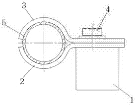
Due to the limitation of production accuracy and the vibration deformation during use, the radius of the arc of the movable clamp 3 is often larger than the radius of the hydraulic oil pipe 5, and the hydraulic oil pipe 5 is only pressed by a point on the inner side of the top of the movable clamp 3, and the left and right are not restricted. The locking of the hydraulic oil pipe 5 is unstable, and it is easy to shake, which will cause deformation, desoldering, perforation of the hydraulic oil pipe 5, and then accidents such as leakage and pipe burst

Method used

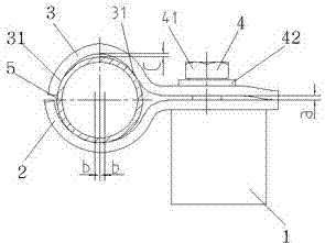
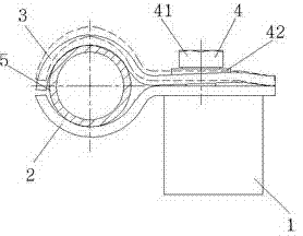

Image

  • Hydraulic oil pipe clamp
  • Hydraulic oil pipe clamp
  • Hydraulic oil pipe clamp

Examples


Embodiment Construction

[0014] The present invention will be further described below in conjunction with drawings and embodiments.

[0015] Such as figure 2 , image 3 As shown, the present invention includes a fixed clamp 2 whose right end is welded on the upper side of the support 1, a movable clamp 3 arranged on the upper side of the fixed clamp 2, and a fastener 4 positioned at the right end of the movable clamp 3, and the support 1 is welded on the construction machinery dynamic On the arm or arm, the fastener 4 includes a fastening bolt 41 and a gasket 42. The right end of the movable clip 3 is fixedly connected with the right end of the fixed clip 2 through the fastener 4. The left end of the movable clip 3 is an upward convex arc structure, and the fixed clip 2. The left end is a concave semicircular arc structure, and the upward convex arc structure at the left end of the movable clip 3 is an elliptical arc structure. The elliptical arc structure is composed of two arcs 31 whose respective...


PUM


Abstract

The invention discloses a hydraulic oil pipe clamp which comprises a fixed clamp, a movable clamp and a fastening member, wherein one end of the fixed clamp is fixed on the upper side of a support, the movable clamp is arranged on the upper side of the fixed clamp, the fastening member is arranged on one end of the movable clamp, one end of the movable clamp is fixedly connected with one end of the fixed clamp through a fastening member, the other end of the movable clamp is of a convex arc-shaped structure, the other end of the fixed clamp is of a concave semi-arc-shaped structure, the convex arc-shaped structure on the other end of the movable clamp is an elliptical arc structure which is combined by two sections of arcs with respectively circle centers horizontally deviating from the symmetric center line of the convex arc shape, the radiuses of the arcs are matched with the radius of a clamped oil pipe, when the other end of the movable clamp is used for clamping the oil pipe, and a gap exists between the highest point on the inner side of the convex arc shape on the upper end of the movable clamp and the highest point of the arc of the oil pipe. The hydraulic oil pipe has a simple structure, is stable and reliable in locking without easily causing vibration, avoids deformation, sealing-off and perforation of the hydraulic oil pipe, and ensures that the whole hydraulic system of engineering machinery normally operates.

Description

technical field [0001] The invention relates to a pipe clamping device, in particular to a hydraulic oil pipe clamping device, which belongs to the technical field of pipe fittings. Background technique [0002] The high-pressure oil output by the hydraulic power unit of construction machinery reaches each actuator through a series of hard pipes and hoses. Due to the structural limitations of construction machinery, the cylinder diameter of the actuator is small, the working pressure reaches 30MPa or more, and the load changes greatly. The working conditions are harsh, and the hydraulic oil pipes often vibrate. Therefore, the reliable fixing of hydraulic oil pipes is particularly important. Hydraulic oil pipes are generally fixed with pipe clamps, and how they are fixed is related to whether construction machinery can work for a long time. Such as figure 1 As shown, the existing hydraulic oil pipe clamp includes a fixed clip 2, a movable clip 3 located on the upper side ...

Claims


Application Information

Patent Timeline
Patent Type & Authority Applications(China)
IPC IPC(8): F16L3/10
Inventor 殷晴飞
Owner 中外合资沃得重工(中国)有限公司
Why Eureka
Eureka Blog
Learn More