
Sectional travel characteristic pneumatic actuator device of turbocharger

A technology of turbocharger and pneumatic actuator, applied in machine/engine, combustion engine, internal combustion piston engine, etc., can solve the problems of linear control only, the cost increases a lot, and the stroke characteristics cannot be segmented.

Active Publication Date: 2012-11-07
康跃科技(山东)有限公司
View PDF6 Cites 3 Cited by
  • Summary
  • Abstract
  • Description
  • Claims
  • Application Information

AI Technical Summary

Problems solved by technology

In the application of variable cross-section turbochargers, its control has always been a big problem. Traditional pneumatic actuators cannot be segmented due to stroke characteristics and can only be controlled linearly, which cannot achieve performance matching under all working conditions. Electronically controlled actuators are used. , the cost will increase a lot, and there are certain problems in reliability. The research and development of a pneumatic actuator with segmented stroke characteristics can realize the organic unity of performance matching, cost and reliability of the variable cross-section turbocharger. The urgent problem that device manufacturers need to solve

Method used


Image

  • Sectional travel characteristic pneumatic actuator device of turbocharger
  • Sectional travel characteristic pneumatic actuator device of turbocharger
  • Sectional travel characteristic pneumatic actuator device of turbocharger

Examples


Embodiment 1

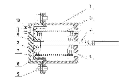
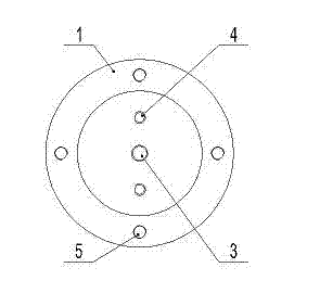
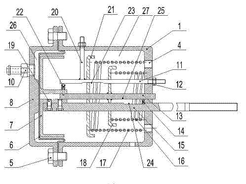
[0045] Example 1, such as image 3 , Figure 4 As shown, a pneumatic actuator device with segmented stroke characteristics of a turbocharger includes an upper casing 8 and a lower casing 1;

[0046] A rubber diaphragm 6 is provided between the upper case 8 and the lower case 1, and the upper case 8 and the lower case 1 are sealed and connected with the rubber diaphragm 6 through bolts 5;

[0047] The rubber diaphragm 6 separates the cavity between the upper casing 8 and the lower casing 1 into two cavities that are not connected to each other: a first cavity 26 and a second cavity 27 .

[0048] The upper casing 8 is provided with an air nozzle 10 communicating with the first cavity 26 .

[0049] A diaphragm seat 7 is provided at a position close to the rubber diaphragm 6 in the second cavity 27, and the main core rod 15 is connected to the diaphragm seat 7;

[0050] One end of the main core rod 15 is fixedly connected with the diaphragm seat 7 through a bolt 19 , and the ot...

Embodiment 2

[0068] Example 2, such as Figure 5 As shown, in the above-mentioned embodiment 1, the diameters of the main spring 16 and the auxiliary spring 17 are the same, the main spring 16 is arranged between the main spring seat 18 and the lower housing 1, and the auxiliary spring 17 is arranged between the main spring seat 18 and the auxiliary spring seat Between 21.

[0069] When working, the gas with pressure enters the first cavity 26 formed by the upper casing 8 and the rubber diaphragm 6 from the gas nozzle 10, and pushes the rubber diaphragm 6 and the diaphragm seat 7 to move toward the lower casing 1, and the diaphragm The seat 7 moves together with the auxiliary core rod 13 through the upper locking pin assembly 22, the auxiliary core rod 13 compresses the main spring 16 through the welded main spring seat 18, and the main core rod 15 moves together with the diaphragm seat 7, Adjust the booster.

[0070] At this time, only the main spring 16 acts, and the travel characteris...


PUM


Abstract

The invention discloses a sectional travel characteristic pneumatic actuator device of a turbocharger, which includes an upper casing and a lower casing, wherein a rubber diaphragm is arranged between the upper and the lower casings, and divides a cavity between the upper and the lower casings into two cavities, namely a first cavity and a second cavity, that are not communicated; a diaphragm seat is arranged in a position inside the second cavity and near to the rubber diaphragm; an auxiliary core bar is connected onto the diaphragm seat; and springs with different elasticity coefficients are mounted on the auxiliary core bar. The sectional travel characteristic pneumatic actuator device can realize the matching of different travel characteristics, so that the performance of the supercharger is adjusted to the optimum as far as possible.

Description

technical field [0001] The invention relates to a turbocharger pneumatic actuator device, in particular to a turbocharger segmented stroke characteristic pneumatic actuator device, which belongs to the field of internal combustion engines. Background technique [0002] With the continuous development of national emission regulations and user needs, the supercharging technology of engines, especially diesel engines, has also made great progress. The structure of the exhaust gas turbocharger has developed from the traditional fixed section to the exhaust gas bypass that can take into account the low-speed torque of the engine. Structural turbochargers. After the implementation of the National III emission regulations, people's demand for engine turbochargers that can take into account the high and low speed performance of the engine has become more and more intense. The variable cross-section turbocharger has become the focus of research and development at home and abroad. ...

Claims


Application Information

Patent Timeline
IPC IPC(8): F02B37/22
CPCY02T10/144Y02T10/12
Inventor 王航桑悟海郭伦海杨恒兴袁道军曹怀瑞
Owner 康跃科技(山东)有限公司
Learn More