
High-resolution orientation resistivity side direction logging instrument and logging method

A high-resolution, resistivity technology, used in wellbore/well components, measurement, earth-moving drilling, etc., can solve the problem of micro-resistivity scanning instruments and scanning imaging around the well. The detection depth is shallow, and the heterogeneous information around the well cannot be extracted. question

Inactive Publication Date: 2012-11-07
THE 22ND RES INST OF CHINA ELECTRONICS TECH GROUP CORP
View PDF7 Cites 8 Cited by
  • Summary
  • Abstract
  • Description
  • Claims
  • Application Information

AI Technical Summary

Problems solved by technology

[0003] The original dual laterolog tool can measure two deep and shallow resistivity curves. This information is the influence of the entire borehole on the measurement results. The heterogeneity information around the well cannot be extracted from the measurement information. Scanning imaging can well analyze the incoming medium near the wellbore, but the detection depth of the micro-resistivity scanning tool and the scanning imaging around the wellbore is very shallow. The 12 azimuth electrodes of the high-resolution azimuth laterolog tool can obtain an Although the resolution of the high-resolution azimuth resistivity is lower than that of the peripheral scanning imager and the micro-resistance scanning imager, its detection depth is far greater than that of the peripheral scanning imager and the micro-resistance scanning imager

Method used


Image

  • High-resolution orientation resistivity side direction logging instrument and logging method
  • High-resolution orientation resistivity side direction logging instrument and logging method
  • High-resolution orientation resistivity side direction logging instrument and logging method

Examples


Embodiment 1

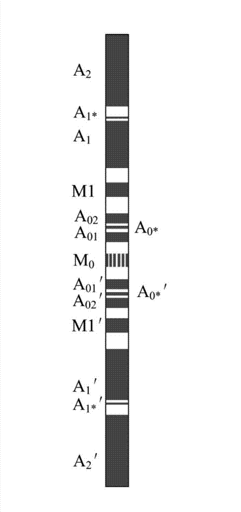
[0039] Embodiment one: see figure 2 . The high-resolution azimuthal resistivity lateral logging instrument of the present invention is composed of an azimuth electrode system and a measurement electronic circuit, and is mainly used for measuring the resistivity of heterogeneous formations in different azimuths around the well. The electrode system of the logging instrument consists of It is composed of multiple lateral electrode rings and azimuth electrode rings M0 with different widths inlaid on the insulating carrier. The center of the electrode system is the azimuth electrode ring M0. The 14 lateral electrode rings with different widths take M0 as the axis of symmetry. Arrangement, the selection of the width and arrangement interval of different lateral electrode rings is based on the condition that the detection depth is 1.0m and the resolution is 0.2m. The ring, the azimuth electrode ring, the reference electrode N and the loop B are connected to the measurement electro...

Embodiment 2

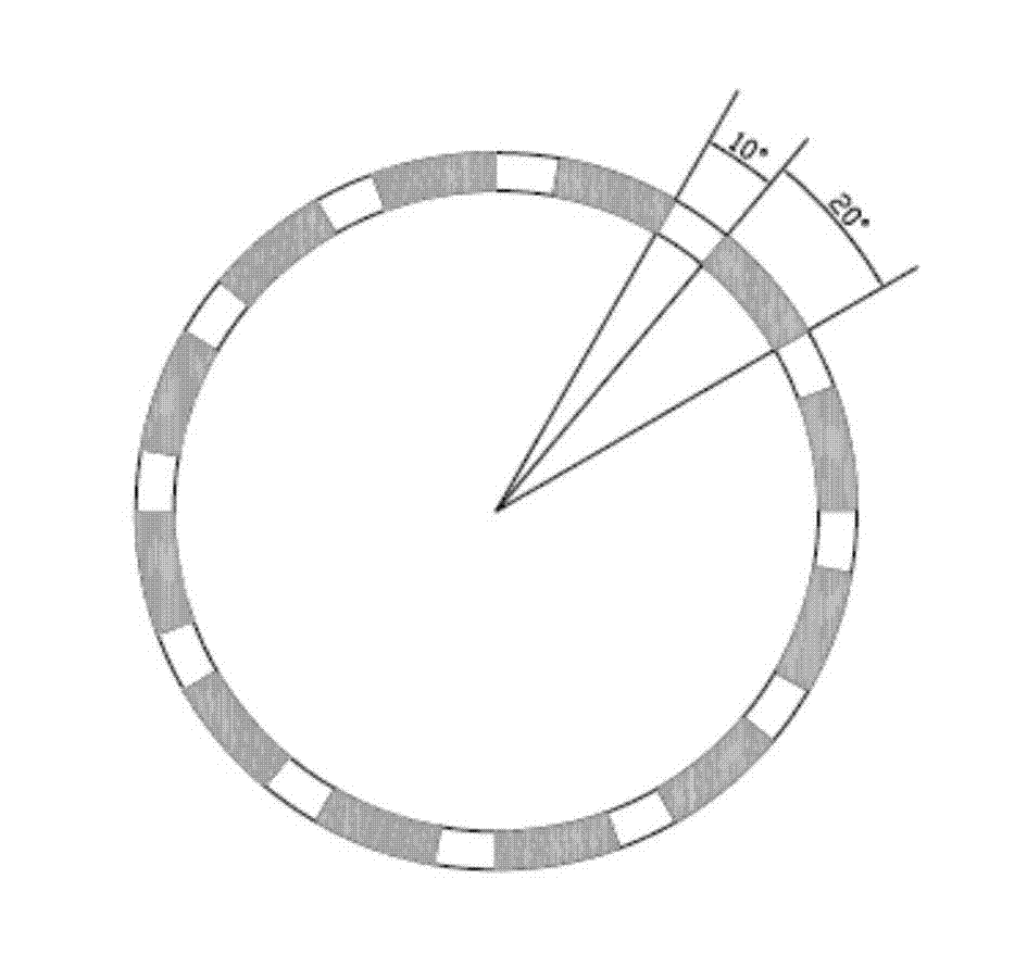
[0041] Embodiment two: see figure 2 , image 3 . In this embodiment, the high-resolution azimuth resistivity lateral logging tool, the azimuth electrodes are arranged as follows image 3 As shown, the azimuth electrode ring M0 consists of 12 coils M0 1 ~M0 12 Composition, its axial resolution is 60°, the width of a single electrode ring is 20 degrees, and the center of each electrode ring is 30 degrees. Each electrode ring is separated by an insulating material.

[0042] The lateral electrode ring is composed of 14 coils arranged symmetrically, with the electrode ring M0 at the center of the insulating carrier as the center, and the outwards are A01, A01', A0 * , A0 * ’, A02, A02’, M1, M1’, A1, A1’, A1 * 、A1 * ', A2, A2', where A01, A01', A0 * , A0 * ’, A02, A02’, M1, M1’, A1, A1’, A1 * 、A1 * ', A2, A2' are electrode rings with the same name respectively, and the electrode rings with the same name are shorted with wires to maintain equipotentiality.

Embodiment 3

[0043] Embodiment three. This embodiment discloses a logging method using the high-resolution azimuth resistivity lateral logging tool.

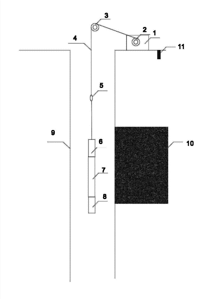
[0044] figure 1 It is a schematic diagram of the logging device and its usage state. In the figure, 9 is the measuring well, and 10 is the formation around the measuring well.

[0045] The device consists of a high-resolution azimuth lateral logging tool and a telemetry nipple 6, etc., wherein the high-resolution azimuth lateral logging tool is composed of an azimuth lateral electrode system and a measurement electronic circuit. The azimuth lateral electrode system 7 and the measurement electronic circuit 8 are suspended in the measurement well through the 7-core cable 4, and the 7-core cable 4 is twisted on the winch drum 2 through the pulley 3, so that the telemetry sub-section 6 and the high-resolution azimuth lateral electrode system 7. The electronic circuit 8 moves up and down in the measuring well, the winch drum 2 is a part of the...


PUM


Abstract

The invention relates to an orientation side direction logging instrument and a logging method. A high-resolution orientation resistivity side direction logging instrument mainly comprises an orientation electrode system and a measurement electronic circuit, wherein the electrode system consists of a plurality of side direction electrode rings which have different widths and are embedded on an insulation carrier and an orientation electrode ring M0; the M0 is arranged in the center of the electrode system; 14 electrode rings with different widths and the M0 are in axial symmetry and arranged at different intervals; each homonymic electrode ring is in short circuit through a wire and kept at the same potential; and the homonymic electrode rings, the orientation electrode ring, a reference electrode N and a loop B are connected with the measurement circuit through wires. By the high-resolution orientation resistivity side direction logging instrument and the logging method, a high-resolution side direction curve and an orientation side direction curve can be measured at the same time, and relatively detail logging information can be supplied to logging evolution; the high-resolution logging instrument can identify a thin layer and a thin mutual layer of which the thickness is 0.2 meter, so that an effective logging curve is supplied to thin layer logging; and cracks and caves can be effectively identified.

Description

technical field [0001] The invention relates to an azimuth lateral logging tool and a logging method, in particular to a high-resolution azimuth resistivity lateral logging tool and a logging method. Background technique [0002] With the gradual deepening of oilfield exploration and development and the further increase of difficulty, the accuracy requirements for reservoir evaluation work are getting higher and higher, and logging tools need to have higher vertical resolution and larger radial detection depth. The ability to cover the entire wellbore and determine formation characteristics in a directional manner enables logging tools to measure more abundant formation information in heterogeneous formations and thin layers. [0003] The original dual laterolog tool can measure two deep and shallow resistivity curves. This information is the influence of the entire borehole on the measurement results. The heterogeneity information around the well cannot be extracted from th...

Claims


Application Information

Patent Timeline
IPC IPC(8): E21B49/00E21B47/00
Inventor 李智强杨志强王军杰杨铖杨艳军鞠成黄毅郑俊祥赵灵宣季秀峰
Owner THE 22ND RES INST OF CHINA ELECTRONICS TECH GROUP CORP
Learn More