Railway T-beam erecting construction method based on continuous beam laying reloading points

A construction method and railway technology, applied in the direction of bridge construction, erection/assembly of bridges, bridges, etc., can solve the problems of many construction equipment and construction personnel, slowing down of beam erection progress, and large construction cost, so as to achieve flexible use methods and reverse engineering. The effect of fast installation and low investment cost

Active Publication Date: 2014-07-23
CHINA RAILWAY FIRST GRP CO LTD
View PDF4 Cites 0 Cited by
  • Summary
  • Abstract
  • Description
  • Claims
  • Application Information

AI Technical Summary

Problems solved by technology

[0006] The technical problem to be solved by the present invention is to provide a railway T-beam erection construction method based on continuous beam layout and replacement points for the above-mentioned deficiencies in the prior art, which has simple construction steps, easy operation, low input cost and erection speed Fast, safe and reliable erection process, which can effectively solve the problems of slow erection progress, low work efficiency, high construction cost, and many construction equipment and construction workers existing in the erection method of inverted T-beam at the bridge head.

Method used


Image

  • Railway T-beam erecting construction method based on continuous beam laying reloading points
  • Railway T-beam erecting construction method based on continuous beam laying reloading points
  • Railway T-beam erecting construction method based on continuous beam laying reloading points

Examples


Embodiment Construction

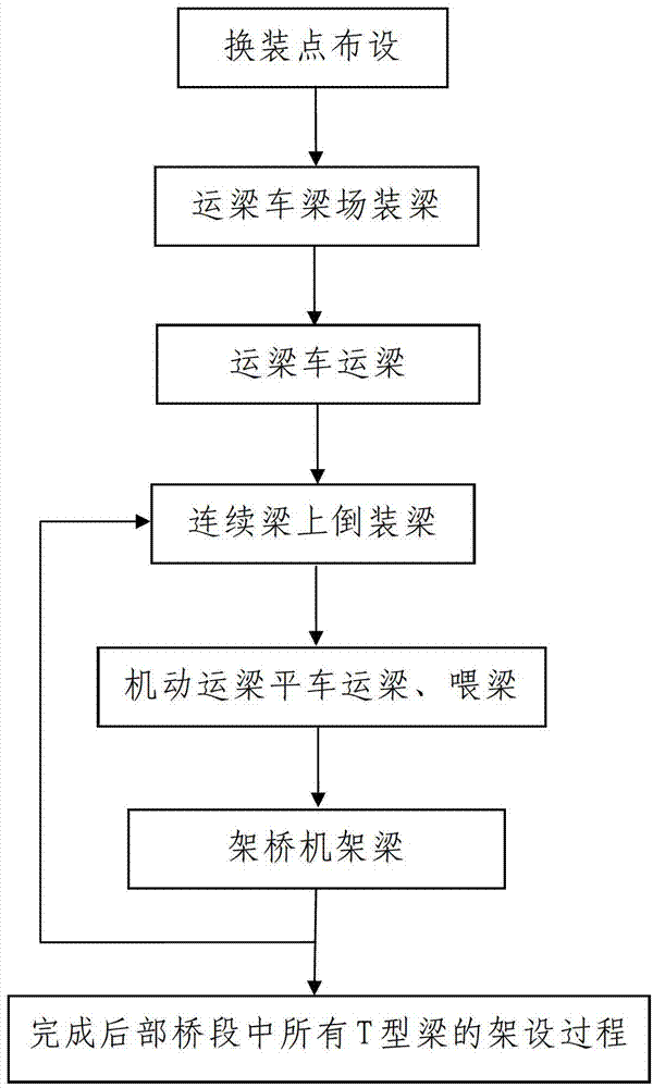
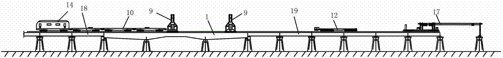
[0054] like figure 1 Shown is a railway T-beam frame construction method based on continuous beam layout and replacement points. The bridge to be constructed is a railway bridge with a bridge length greater than 2km and a railway track laid on it. The bridge to be constructed includes the completed front The first bridge section 18, the unfinished rear bridge section 19 behind the front bridge section 18, and the middle bridge section 1 connected between the front bridge section 18 and the rear bridge section 19 and completed, the The middle bridge section 1 is a continuous beam, and the rear bridge section 19 is composed of multiple T-beams assembled. The bridge structure constructed is detailed in figure 2 .

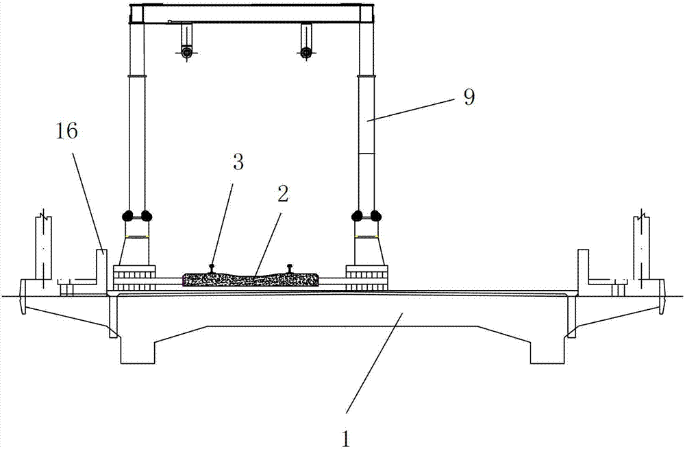
[0055] In this embodiment, the railway track includes two steel rails 3 arranged along the bridge direction, and the two steel rails 3 are paved on the concrete sleeper 2, and a layer of stone ballast leveling layer 4 is installed on the bottom of the concrete sleepe...


PUM


Abstract

The invention discloses a railway T-beam erecting construction method based on continuous beam laying reloading points. A construction bridge comprises a front bridge section, a middle bridge section and a rear bridge section. The method comprises a first step of laying reloading points, and laying temporary reloading devices on the middle bridge section, a second step of loading beams on a beam transporting vehicle in a beam field; a third step of utilizing the beam transporting vehicle to transport the beams, and transporting T-beams to be erected to the reloading points; a fourth step of inversely loading the beams at the position of a continuous beam, and enabling the T-beams to be erected to be inversely loaded on a maneuvering beam-transporting flatcar; a fifth step of utilizing the maneuvering beam-transporting flatcar to transport the beams, and transporting the T-beams to be erected to be transported forwards to the position of a bridge erecting machine to feed the beams; a sixth step of utilizing the bridge erecting machine to erect the beams, and a seventh step of repeating the fourth step to the sixth step many times, and finishing the erecting process of all T-beams in the rear bridge section. The railway T-beam erecting construction method is simple in construction steps, simple and convenient to operate, low in input cost, quick in erecting speed and safe and reliable in the erecting process and can solve the problems that in an existing erecting method for inversely loading the T-beams at a bridgehead, the beam erecting progress is reduced, the working efficiency is low, the construction cost is high, and required construction devices and construction workers are too many, and the like.

Description

technical field [0001] The invention relates to a T-shaped beam erection construction method, in particular to a railway T-shaped beam erection construction method based on the arrangement of replacement points for continuous beams. Background technique [0002] During the construction of railway laying, bridge erecting machines, locomotives, flatbed cars and other supporting large equipment are usually used for laying. The span of the erected T-beam (referring to the beam with T-shaped cross-section) is generally 32 meters, and the weight of each T-beam is about 160T. In actual erection, a special beam truck is generally used for transportation. The frame base is generally set close to the existing line. At present, the railway lines under construction are characterized by a large number of bridges, and the length of the bridges accounts for a large percentage of the total length of the line. Among them, there are more and more new railways spanning existing railways, hig...

Claims


Application Information

Patent Timeline
Patent Type & Authority Patents(China)
IPC IPC(8): E01D21/06
Inventor 向淑智韩连军杨宏伟李建国丁见明曹德志王勇刘山社林彦军张水洲张献廷魏奇武小云
Owner CHINA RAILWAY FIRST GRP CO LTD
Why Eureka
Try Eureka