
Adaptive surrounding view monitoring apparatus and method thereof

A monitoring device and surrounding field technology, applied in optical observation devices, transportation and packaging, TV, etc., can solve the problems of dead angles, blind angles of vision, distortion, etc., and achieve the effect of increasing width, widening field of view, and eliminating blind angles

Inactive Publication Date: 2012-10-17
IND TECH RES INST
View PDF8 Cites 13 Cited by
  • Summary
  • Abstract
  • Description
  • Claims
  • Application Information

AI Technical Summary

Problems solved by technology

[0007] 2. The bird's-eye view images around multiple vehicles are not connected, so the bird's-eye view images with dead angles are presented
[0009] 4. It can only display images in a single direction or in two directions at the same time, but cannot display images in adjacent directions, resulting in blind spots in the field of vision
[0010] To sum up the above, the existing technology or commercialized system has the disadvantages of distortion, presenting a bird's-eye view picture with dead angles, requiring the use of additional devices, and being unable to present pictures in adjacent directions

Method used


Image

  • Adaptive surrounding view monitoring apparatus and method thereof
  • Adaptive surrounding view monitoring apparatus and method thereof
  • Adaptive surrounding view monitoring apparatus and method thereof

Examples


Embodiment Construction

[0058] Embodiments of the present disclosure are described below through specific examples, and those skilled in the art can easily understand other advantages and effects of the present disclosure from the content disclosed in this specification.

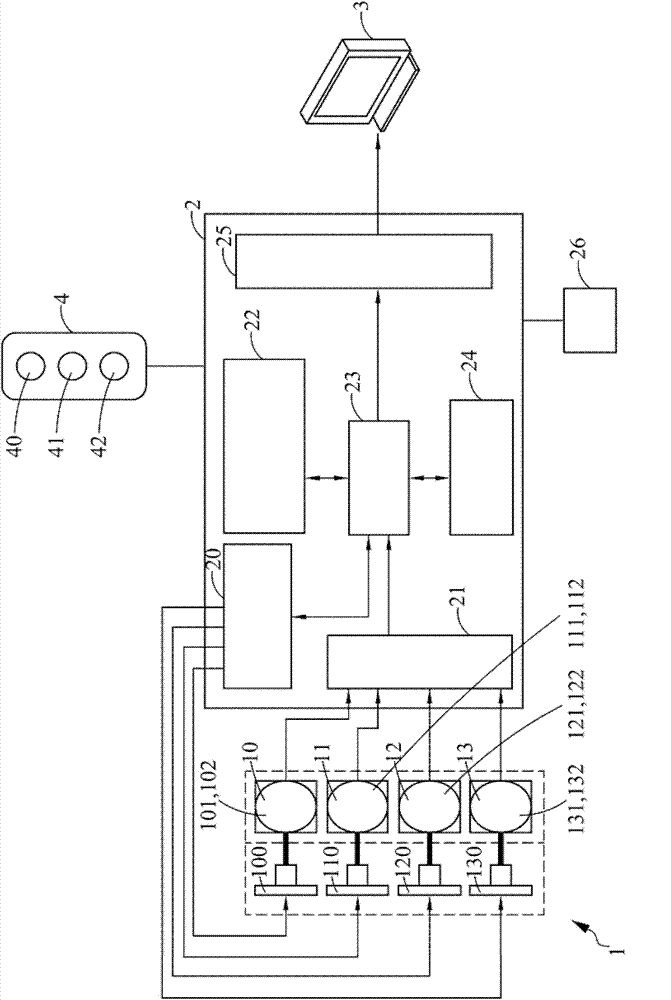
[0059] see figure 1 As shown, the present disclosure is a surrounding field monitoring device, which has a steering camera device group 1 , a control unit 2 , a display device 3 and a mode switching switch 4 .

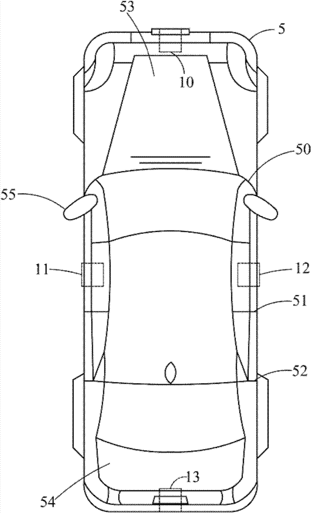
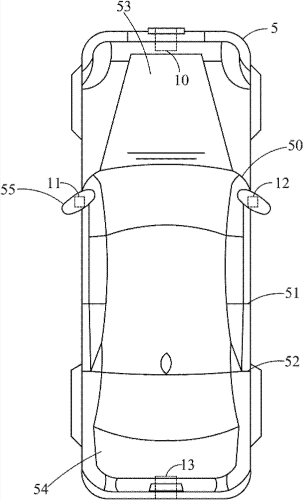
[0060]The steerable camera set 1 has a plurality of steerable camera devices 10, 11, 12, 13, and the steerable camera devices 10, 11, 12, 13 have a micro-processing unit 100, 110, 120, 130, a motor module 101, 111, 121, 131 and an image sensor 102, 112, 122, 132, motor modules 101, 111, 121, 131 are electrically connected to microprocessing units 100, 110, 120, 130, and motor modules 101, 111, 121, 131 are connected to The image sensor 102, 112, 122, 132, so that the image sensor 102, 112, 122, 132 can be rotated to the de...


PUM


Abstract

An adaptive surrounding view monitoring apparatus and a method thereof are disclosed, in which the apparatus uses a steerable camera set to take horizontal images while sending the horizontal images to a control unit where they are combined into an image of 180-degree or 360-degree surrounding view. It is noted that the surrounding view image maybe an image of front surrounding view, an image of rear surrounding view or an image of ambient surrounding view relating to a vehicle, and using that, visual blind spot of a driver driving the vehicle can be eliminated and the field of vision is widened, and thereby, the probability of accident occurring is reduced.

Description

technical field [0001] A surrounding field monitoring device and its method (ADAPTIVE SURROUNDING VIEW MONITORING APPARATUS AND METHOD THEREOF), which provides a steering camera device group for horizontal photography and a control unit (controlling unit) capable of generating surrounding field images, and through the surrounding field The image output can eliminate the blind spots of the driver's vision and increase the width of the field of view to reduce the probability of accidents. Background technique [0002] In order to clearly point out the internal position of the current car body, the column between the windshield and the left and right rearview mirrors of the car body is called the A-pillar, and the column between the front seat and the rear seat of the car body is called the A-pillar. The B-pillar, if viewed from the inside of the car body, the seat belts are mostly set at the B-pillar, and the two sides of the headrest of the rear seat are called the C-pillar. ...

Claims


Application Information

Patent Timeline
Patent Type & Authority Applications(China)
IPC IPC(8): H04N7/18B60R11/04
CPCH04N7/181B60R2300/605B60R2300/802B60R1/00B60R1/23B60R1/28
Inventor 沈信良郑国祥段宗廷张晏树
Owner IND TECH RES INST
Learn More