
Liquid crystal display device with transmissive and reflective units

A technology of liquid crystal display device and liquid crystal display unit, which is applied in static indicators, nonlinear optics, instruments, etc., can solve the problem of low similarity, and achieve the effect of increasing the utilization rate of light

Inactive Publication Date: 2012-10-17
INNOLUX CORP
View PDF5 Cites 2 Cited by
  • Summary
  • Abstract
  • Description
  • Claims
  • Application Information

AI Technical Summary

Problems solved by technology

This structural design has the problem of low similarity between the Voltage-Transmittance curve and the Voltage-Reflective curve

Method used


Image

  • Liquid crystal display device with transmissive and reflective units
  • Liquid crystal display device with transmissive and reflective units
  • Liquid crystal display device with transmissive and reflective units

Examples


Embodiment Construction

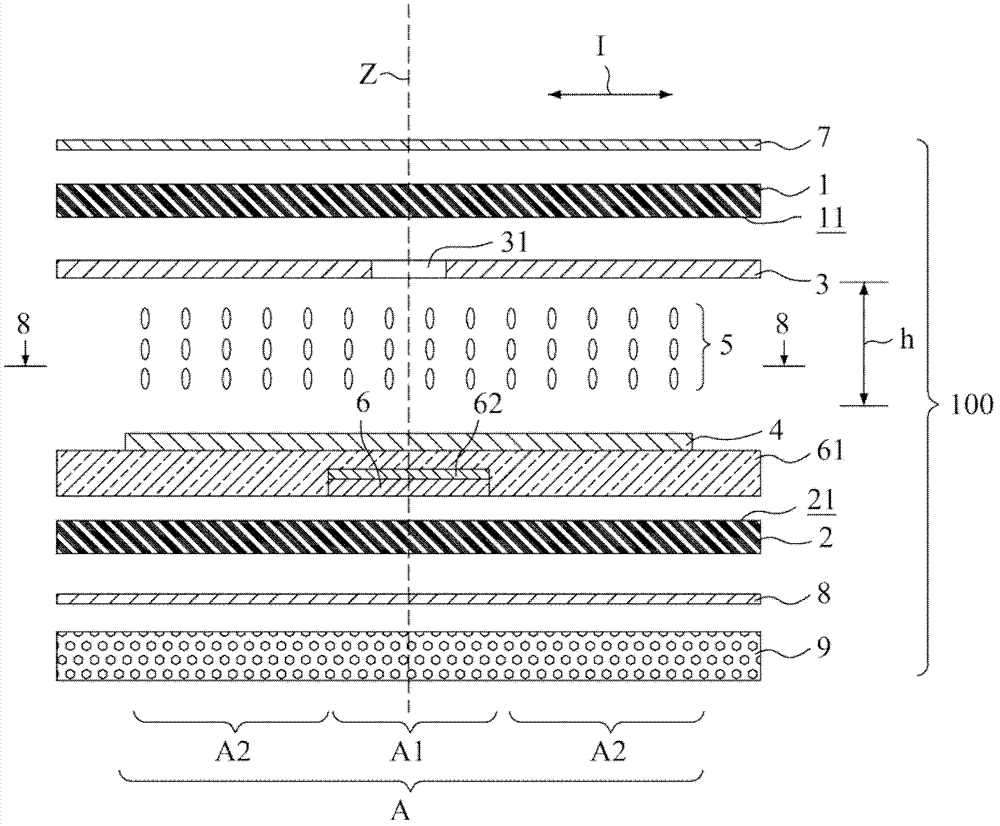
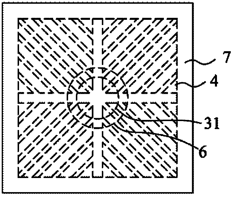
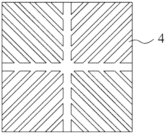
[0053] refer to figure 1 and figure 2 as shown, figure 1 A schematic cross-sectional view showing a first embodiment of the present invention, figure 2 show figure 1 top view. This embodiment takes Twisted-Vertical aligned Mode (TVA mode) as an example (a pixel (pixel) can be composed of a liquid crystal display unit or a plurality of liquid crystal display units). The liquid crystal display device 100 having a transmissive area and a reflective area in this embodiment includes a first substrate 1 extending along an extending direction I and parallel to each other, a second substrate 2 corresponding to the first substrate, a first substrate 2 An electrode 3 and a second electrode 4 corresponding to the first electrode 3 . There is a predetermined distance h between the first substrate 1 and the second substrate 2 .

[0054]A liquid crystal layer 5 is interposed between the first electrode 3 and the second electrode 4 . The liquid crystal layer 5 can be a negative type...


PUM


Abstract

A liquid crystal display device with transmissive and reflective units is provided. At least a bare unit is formed in a predetermined portion of the first electrode. A reflective layer is disposed on the second electrode at a location corresponding to the bare unit. A liquid crystal display unit is defined in an extension direction between the second and first electrodes. The liquid crystal display unit has a portion corresponding to the bare unit and defined as a reflective unit and another portion that surrounds outside the reflective unit and defined as a transmissive unit. The liquid crystal layers show an effective electrical field that is weaker within the reflective unit than within the transmissive unit. The transmissive unit has a circumferential edge portion spaced away from the reflective unit and forming an additional reflective unit for the liquid crystal display unit.

Description

technical field [0001] The invention relates to a structural design of a liquid crystal display device, in particular to a liquid crystal display device with transmission and reflection. Background technique [0002] Liquid crystal display devices have become indispensable output devices in various fields at present. A typical liquid crystal display device mainly includes a pair of substrates, a pair of electrodes, and a liquid crystal layer located between the electrodes. The liquid crystal layer includes liquid crystal molecules. [0003] In order to maintain the best display quality of the liquid crystal display in a bright environment, various transflective structures have been designed by the industry. For example, some practitioners use different liquid crystal layer thicknesses in the liquid crystal layer gaps in the transmissive area and the reflective area. Such structural design has the problems of complex manufacturing process and low yield. [0004] In the st...

Claims


Application Information

Patent Timeline
Patent Type & Authority Applications(China)
IPC IPC(8): G02F1/1335G02F1/1343G02F1/13363G02F1/133
CPCG02F2001/133742G02F1/134309G02F1/133707G02F1/133555G02F1/133742
Inventor 彭政忠李欣达
Owner INNOLUX CORP
Learn More