V-shaped valve for measuring and controlling flow

A flow measurement and valve plate technology, which is applied to safety valves, balance valves, valve devices, etc., can solve problems such as the inability to meet the accuracy of flow control in precise aeration systems, poor linearity of air conditioning, and failure to meet energy-saving requirements. To achieve the effect of good air conditioning linearity, large flow adjustment range and simple structure

Inactive Publication Date: 2012-10-17
WUXI GL TUBRO COMPRESSOR
View PDF5 Cites 2 Cited by
  • Summary
  • Abstract
  • Description
  • Claims
  • Application Information

AI Technical Summary

Problems solved by technology

This flowmeter belongs to the temperature difference flowmeter. Its principle is to obtain the change of the gas flow rate through the temperature change of the detection head. Due to the complexity of the pressure air movement in the pipeline and the unevenness of the temperature distribution, this type of flow rate is determined. The measurement accuracy of the meter is low and the stability is poor, which cannot meet the accuracy of the flow control of the precise aeration system
At the same time, the flow path of ordinary control valves is circular, and when the valve plate is opened and closed, the linear relationship between the flow change and the valve plate opening is poor, so there is also the disadvantage of poor linearity of air conditioning, which cannot meet the ideal energy-saving requirements

Method used


Image

  • V-shaped valve for measuring and controlling flow
  • V-shaped valve for measuring and controlling flow
  • V-shaped valve for measuring and controlling flow

Examples


Embodiment Construction

[0015] Below the present invention will be further described in conjunction with accompanying drawing:

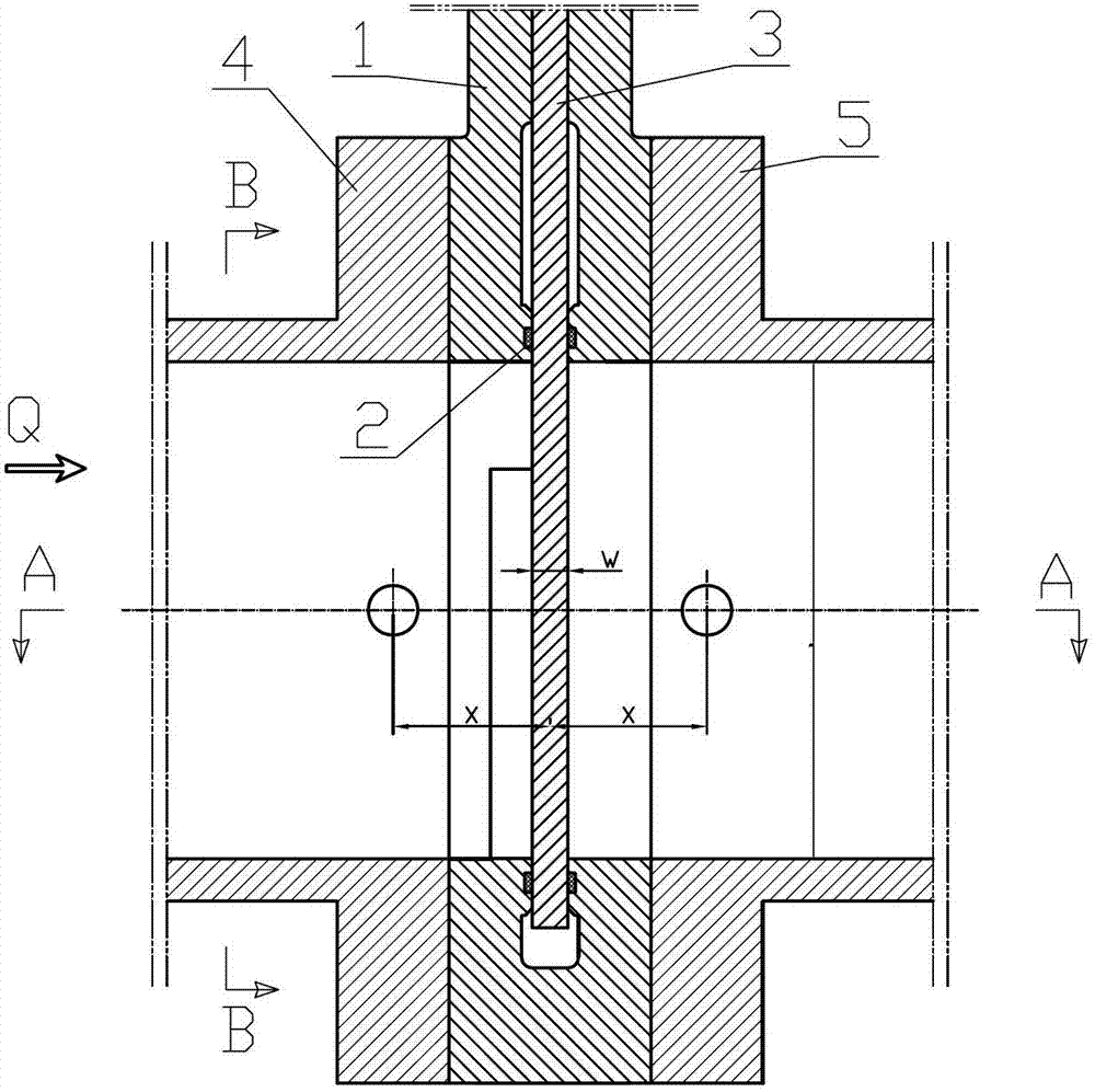
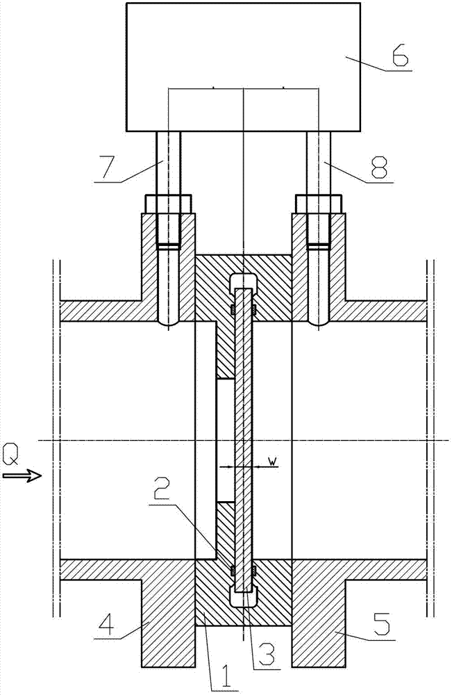
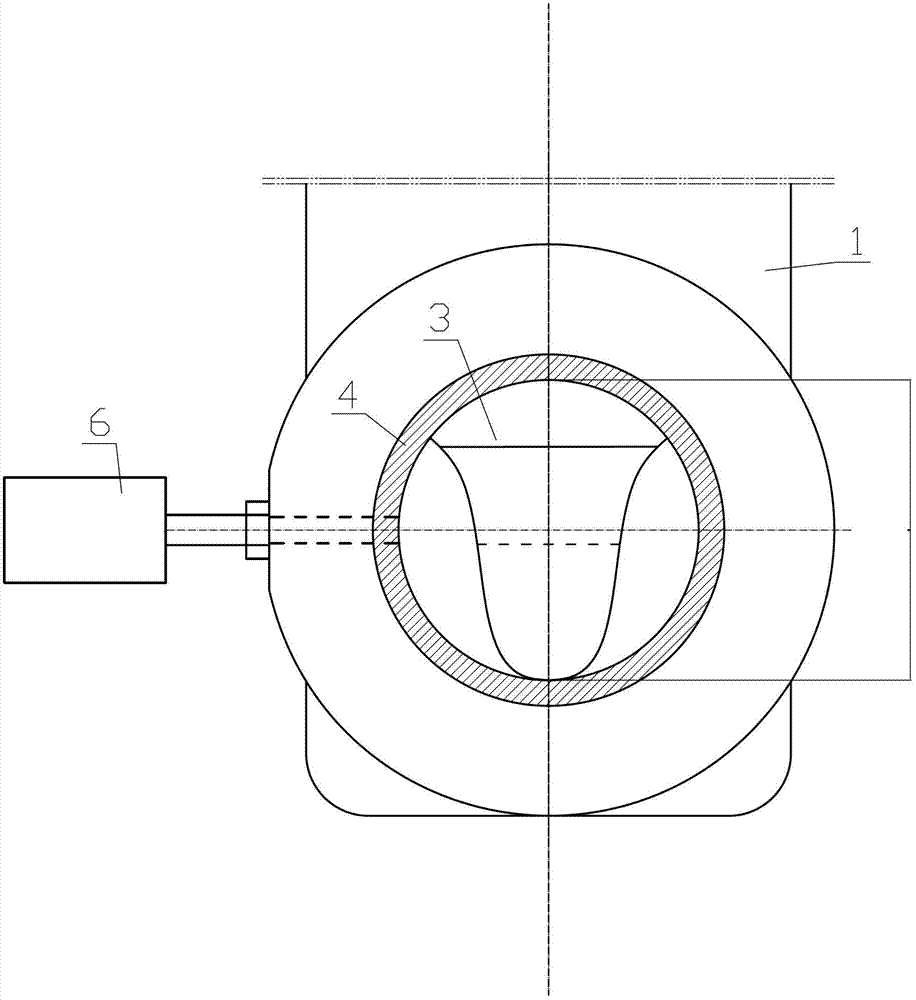
[0016] Such as figure 1 , figure 2 , image 3 As shown: it includes valve body 1, sealing ring 2, valve plate 3, valve front pipe 4, valve rear pipe 5, air differential pressure transmitter 6, positive pressure connecting pipe 7, negative pressure connecting pipe 8, etc.

[0017] The valve body 1 is equipped with a valve plate 3 , and a sealing ring 2 is arranged on the valve body 1 . The positive pressure interface of the air differential pressure transmitter 6 is connected to the inner cavity of the pipeline 4 before the valve through the positive pressure connecting pipe 7, and the negative pressure interface of the air differential pressure transmitter 6 is connected to the valve after the valve through the negative pressure connecting pipe 8. The inner cavity of the pipeline 5 is connected, the pipeline 4 before the valve is arranged at the front end of the valve b...


PUM


Abstract

The invention relates to a V-shaped valve for measuring and controlling flow, and particularly relates to a special device for accurately measuring and controlling the flow of air on a wastewater treatment and accurate aeration system. The V-shaped valve comprises a valve body, a valve plate, a valve front pipeline, a valve back pipeline and an air difference pressure transmitter, wherein the valve plate is installed in the valve body and the valve body is provided with a sealing ring. The V-shaped valve is characterized in that a positive pressure joint of the air difference pressure transmitter is connected with an inner cavity of the valve front pipeline through a positive pressure joint pipe, a negative pressure joint of the air difference pressure transmitter is connected with an inner cavity of the valve back pipeline through a negative pressure joint pipe, the valve front pipeline is arranged at the front end of the valve body, and the valve back pipeline is arranged at the back end of the valve body. The V-shaped valve is good in stability, large in flow regulation range and high in metering accuracy, and can completely satisfy the requirements of the wastewater treatment and accurate aeration system on immediate regulation of the air flow; and according to the V-shaped valve disclosed by the invention, flow variation and the opening of the valve plate show a better linear relationship, so that the V-shaped valve has good air regulation linearity.

Description

technical field [0001] The invention relates to a V-shaped valve for flow measurement and control, in particular to a special device for precise measurement and control of air flow in a sewage treatment precision aeration system, and belongs to the technical field of mechanical structures. Background technique [0002] In the existing technology, in the precise aeration system of sewage treatment, the control valve and the gas flow meter are installed in series. The flow meter is located on the outlet pipeline close to the control valve, and the signal detected by the flow meter is fed back to the intelligent automatic control system. , the control system will input the command corresponding to the process requirements into the control valve, so that the control valve will act to realize the real-time adjustment of the flow, so as to meet the different requirements of the air flow in each stage of the sewage treatment process. This flowmeter belongs to the temperature differ...

Claims


Application Information

Patent Timeline
Patent Type & Authority Applications(China)
IPC IPC(8): F16K17/20C02F7/00
CPCY02W10/10
Inventor 金华明
Owner WUXI GL TUBRO COMPRESSOR
Why Eureka
Try Eureka