
Device and method for operating vehicle

A vehicle operation and vehicle technology, applied in the direction of control devices, vehicle accessories, vehicle components, etc., can solve the problem of no suitable man-machine interface

Inactive Publication Date: 2012-10-17
ROBERT BOSCH GMBH
View PDF8 Cites 7 Cited by
  • Summary
  • Abstract
  • Description
  • Claims
  • Application Information

AI Technical Summary

Problems solved by technology

The downside of this is that there is usually no suitable Human Machine Interface (HMI) in order to provide the driver with this information in a reliable manner so that the driver is not distracted by traffic

Method used


Image

  • Device and method for operating vehicle
  • Device and method for operating vehicle
  • Device and method for operating vehicle

Examples


Embodiment Construction

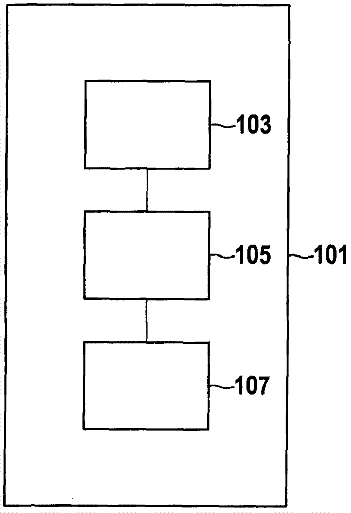
[0020] figure 1 A device 101 for operating a vehicle (not shown) is shown. The vehicle may be, for example, an electric vehicle, a vehicle with an internal combustion engine, or a hybrid vehicle. The device 101 includes a navigation system 103, which can provide information on driving routes. The navigation system 103 is connected to an ideal speed regulation device 105 , which automatically predetermines or calculates the ideal speed of the vehicle on the basis of the provided driving route information. Furthermore, a vehicle speed control device 107 is connected to the ideal speed regulation device 105 . Therefore, advantageously, it is realized that the vehicle speed control device can control the vehicle speed according to a predetermined ideal speed.

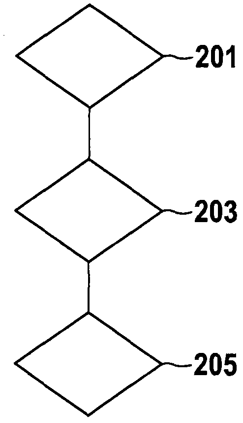
[0021] figure 2 A flowchart of a method for operating a vehicle is shown. In step 201, the ideal speed of the vehicle is automatically pre-determined according to the travel section information. Then in step 203, the...


PUM


Abstract

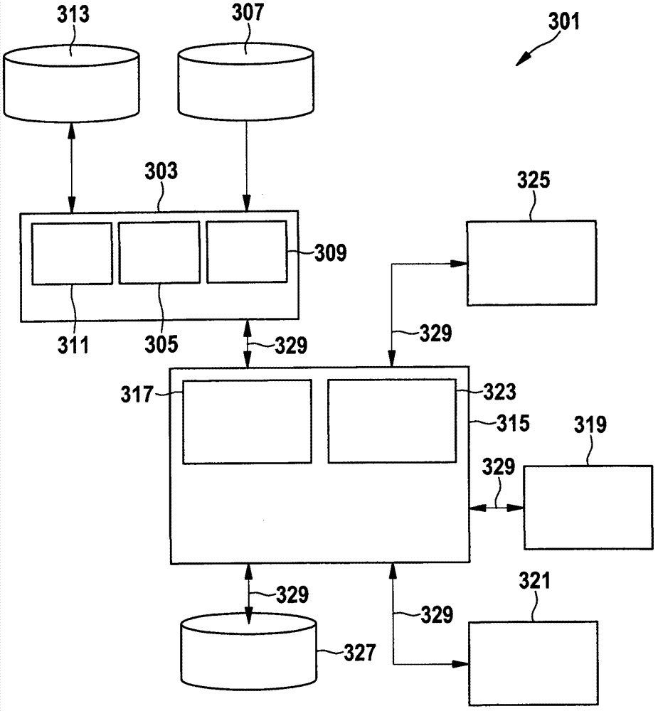
The invention relates to a device (301) for operating a vehicle, specifically a device for operating an electric vehicle. The device is provided with a navigation system (303) for providing the travelling road information, and an ideal speed adjusting device (317) which is connected with the navigation system (303) and is used for automatically predetermining the ideal speed of the vehicle according to the travelling road information. The invention also relates to a method for operating a vehicle.

Description

technical field [0001] The invention relates to a device and a method for operating a vehicle. Background technique [0002] Usually the navigator predetermines for the driver, for example, how fast he must drive or when he must brake before a curve in order to save fuel in the case of a vehicle with an internal combustion engine or electricity in the case of an electric vehicle. A disadvantage of this, however, is that there is usually no suitable Human Machine Interface (HMI, Human Machine Interface) in order to provide the driver with this information in a reliable manner, so that the driver is not distracted by the traffic. [0003] A method for calculating a fuel-minimizing route for a vehicle with an internal combustion engine is known from publication DE 10 2009 024 528 A1, in which a cost-optimized route is calculated taking fuel prices into account. [0004] A similar method is known from publication WO 2010021982 A2, in which a fuel-saving route is calculated with...

Claims


Application Information

Patent Timeline
IPC IPC(8): B60K31/00B60W30/16
CPCB60K31/00B60W30/18154B60W40/13B60W10/18B60W2550/402B60W30/14B60W10/06B60W50/0097B60W2030/1809B60W40/105B60W30/143G01C21/36B60W10/08B60W2720/10B60W30/16G01C21/34B60W2556/50
Inventor W·珀尔施米勒
Owner ROBERT BOSCH GMBH
Learn More