
Welding method for use in high-quality steel continuous rolling

A welding method and high-quality steel technology, applied in welding equipment, arc welding equipment, manufacturing tools, etc., can solve problems such as troublesome operation, broken belts, and restrictions on enterprise development, and achieve the effects of low cost, convenient use, and simple operation

Active Publication Date: 2012-10-17
ANHUI CHUJIANG SPECIAL STEEL CO LTD
View PDF4 Cites 3 Cited by
  • Summary
  • Abstract
  • Description
  • Claims
  • Application Information

AI Technical Summary

Problems solved by technology

[0003] Faced with the continuous improvement of rolling equipment, continuous rolling technology is becoming more and more extensive. Its advantages lie in mass production and processing, cost reduction, and convenient operation. However, there is a kind of rolling equipment that has not changed over time—four-roll single Rolling mill, this type of rolling mill is particularly prominent in the field of high-quality steel, and it is also the most widely used type of high-quality steel processing in many small and medium-sized enterprises. However, the continuous rolling process of high-quality steel faces some obstacles, mainly in It is impossible to weld high-quality steel strips together for continuous rolling, and the welded parts are prone to strip breakage. If continuous rolling is carried out by punching and threading, the operation is very troublesome, which has led many small and medium-sized enterprises to use a single rolling mill for rolling. It is not conducive to the improvement of production efficiency and limits the development of enterprises

Method used


Image

  • Welding method for use in high-quality steel continuous rolling
  • Welding method for use in high-quality steel continuous rolling

Examples


Embodiment Construction

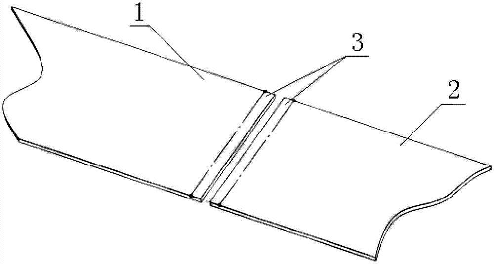
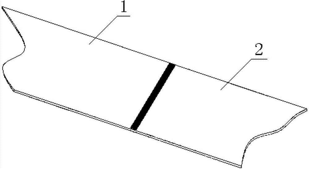
[0025] use figure 1 The two high-quality steel strips to be welded are illustrated, and the welding methods for continuous rolling of high-quality steel include:

[0026] 1) Perform an annealing process on the high-quality steel strip to be welded before welding;

[0027] 2) Put the tail end of the first high-quality steel strip 1 fed into the spiral looper device and the head end of the second high-quality steel strip 2 that has just been sent to the frame material on the welding platform;

[0028] 3) Use the pressure plate on the welding platform to press the end of the high-quality steel strip to ensure that the steel strip will not move;

[0029] 4) Utilize the injection-suction cutting torch to uniformly heat the heating area 3 at the end of the two high-quality steel strips, and at the same time, heat the end faces of the first high-quality steel strip 1 and the second high-quality steel strip 2 Heating back and forth to ensure uniform heating;

[0030] 5) Use argon a...


PUM


Abstract

The invention discloses a welding method for use in high-quality steel continuous rolling, which comprises: 1) annealing the high-quality steel strips to be welded before welding; 2) placing the tail end of the high-quality steel strips delivered to a spiral loop device and the front end of a high-quality steel strips just placed on a conveying frame on a welding platform; 3) pressing the end part of the high-quality steel strips by using a pressure plate on the welding platform in order to ensure that the steel strips does not move; 4) heating the end parts of two high-quality steel strips uniformly by using injection-type torches for cutting, simultaneously heating the end faces of the high-quality steel strips forth and back, and ensuring uniform heating; 5) welding the heated high-quality steel strips by argon arc welding; 6) heating the welded part uniformly by using the injection-type torches for cutting; and 7) naturally cooling the high-quality steel strips, and releasing the pressure plate after the hot red color of the part to be welded fades for 2 to 5 minutes. By the method, a phenomenon that the high-quality steel strips break in a continuous rolling process is avoided.

Description

technical field [0001] The invention relates to a continuous rolling process used in cold-rolled steel strips, in particular to a welding method for steel strips used in high-quality steel continuous rolling. Background technique [0002] Cold-rolled steel strip is the most common rolling process for modern steel strip extension processing metals. It has been a hundred years since the advent of single-rolling mills. Rolling equipment is constantly making breakthroughs, from single-rolling mills to continuous rolling mills. With the technological breakthrough from double rolls to multi-set rolls, the current four-roll reversing mill has stopped in the production of high-quality steel. Most of the early cold-rolled strip equipment was imported from abroad. With the rapid development of the economy since the reform and opening up, many enterprises in my country have invested in the research and development and production of cold-rolled equipment, and the technology and equipmen...

Claims


Application Information

Patent Timeline
IPC IPC(8): B23K9/16B23K9/235
Inventor 龚立品唐时葵圣祥孙乐平刘良庆
Owner ANHUI CHUJIANG SPECIAL STEEL CO LTD
Learn More