Monopulse antenna angle simulation tracking method
A technology of antenna angle and single pulse, applied in the field of aircraft measurement and control, can solve the problem of lack of low cost of measurement and control system, and achieve the effect of normal self-tracking and good tracking performance of servo system
- Summary
- Abstract
- Description
- Claims
- Application Information
AI Technical Summary
Problems solved by technology
Method used
Image
Examples
Embodiment Construction
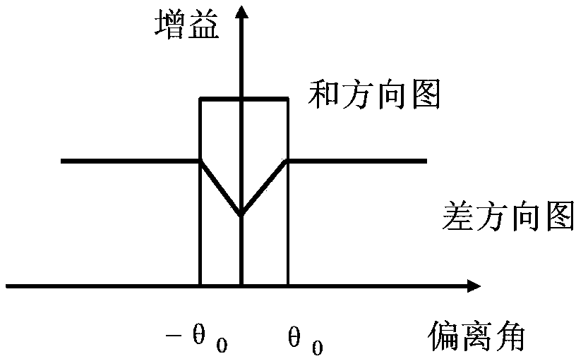
[0025] refer to figure 1 . Most of the dual-channel monopulse tracking system antennas in the measurement and control station adopt multi-mode feed structure, and the mathematical modeling of the angle error signal of the dual-channel monopulse system is carried out. When receiving a single-frequency signal, the XOY plane measurement coordinate system is established with the center of the three axes of the antenna as the origin. When the angle error θ is small, the sum signal (Σ) received by the antenna can be expressed by formula (1):
[0026] the s Σ (t)=Acosω c t (1)
[0027] The differential signal (Δ) can be expressed by formula (2):
[0028]
[0029] where: ω c is the single-frequency signal frequency, A is the signal amplitude, μ is the antenna normalized difference slope, θ is the angle between the incident radio wave and the electric axis of the antenna, is the angle between the projection of the incident radio wave on the XOY plane and the X axis.
[0030]...
PUM
 Abstract
Description
Claims
Application Information
 - R&D
- Intellectual Property
- Life Sciences
- Materials
- Tech Scout
- Unparalleled Data Quality
- Higher Quality Content
- 60% Fewer Hallucinations
Browse by: Latest US Patents, China's latest patents, Technical Efficacy Thesaurus, Application Domain, Technology Topic, Popular Technical Reports.
© 2025 PatSnap. All rights reserved.Legal|Privacy policy|Modern Slavery Act Transparency Statement|Sitemap|About US| Contact US: help@patsnap.com


