Manual multifunctional wire tightening device and a wire tightening method

A multi-functional, wire-tightening technology, applied to overhead lines/cable equipment, etc., can solve the problems of high risk factor, high cost, inconvenient operation, etc., and achieve the effect of safe and reliable construction, flexible construction and transportation, and reduced rotational force.

Active Publication Date: 2017-03-29
STATE GRID CORP OF CHINA +3
View PDF9 Cites 1 Cited by
  • Summary
  • Abstract
  • Description
  • Claims
  • Application Information

AI Technical Summary

Problems solved by technology

The erection construction tightening equipment that existing electric power overhead line adopts is generally: motorized winch or artificial millstone, and motorized winch mill, artificial millstone are very heavy, and electric power overhead line often needs to be carried out in lofty mountains, and these places carry various This kind of power equipment and facilities can only be carried out manually, the work is labor-intensive, the risk factor is high, and the cost is very high.
Even in places where traffic can reach, these facilities also have the disadvantages of inconvenient operation, time-consuming and labor-intensive

Method used


Image

  • Manual multifunctional wire tightening device and a wire tightening method

Examples


Embodiment 1

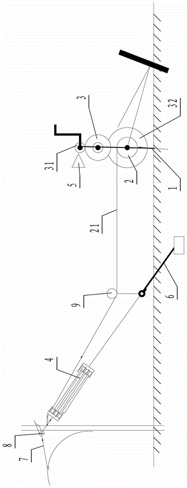
[0030] a kind of like figure 1 The shown manual multi-function tightening device includes a frame 1, a rope reel 2, a gear transmission 3 and a pulley block 4. The rope reel is rotatably supported on the frame, and the rope reel and the gear transmission group Transmission connection, the gear shift is a speed-up gear set, the final gear 32 in the gear shift set is coaxial with the rope reel to drive the rope reel to rotate, and the first stage gear 31 in the gear shift set is manually controlled by the handle. Drive, the anti-reverse device 5 that is used to prevent the reverse rotation of the gear is also provided on the multi-function tensioning device, the traction rope 21 on the rope reel will be wound on the pulley block when working, and one end of the pulley block is fixed on the backguy during work. On the pile anchor 6, the other end of the pulley block is then connected with the stay rope 7, and the other end of the stay rope walks around the fixed pulley 8 for tran...

Embodiment 2

[0033] A wire tightening method, (1) select a flat ground near the wire tightening tower, lay down a fixed pile, install a multifunctional wire tightening device, and make the rope reel of the wire tightening device perpendicular to the pulling rope;

[0034] (2) After connecting both sides of the frame of the multifunctional wire tightening device with a shackle and a wire rope, fix the wire rope to the fixed pile.

[0035] (3) Pull out the traction rope on the rope reel and wind it around the pulley block according to the required traction force:

[0036] (4) In front of the rope reel, install the fixed pulley for bypassing the traction rope by using the anchor of the guy pile of the line tension rod;

[0037] (5) Suspend the fixed pulley for transition on the tower on the side of the wire to be pulled;

[0038] (6) Hang one end of the "pulley block" wrapped around the traction rope on the guy pile anchor of the line tower;

[0039] (7) Clamp the "wire clamp" to the wire t...


PUM


Abstract

The invention discloses a manual multifunctional wire tightening device and a wire tightening method. The device comprises a rack, a rope winding drum, a gear transmission and a pulley block. According to the manual multifunctional wire tightening device and the wire tightening method which are disclosed by the invention, the speed is changed by a gear and the pulley block and the tractive force is reduced, so that the hand-cranking and manual rotating force is greatly reduced and the weight of a machine body is only about 30kg and is flexible to construct and carry. The traction operation can be carried out by a single person in a hand-cranking and manual mode at the position far away from a strain power pole or a hoisting device by over ten meters; and the manual multifunctional wire tightening device is different from the heavy weight of a conventional maneuvering winching machine and the time wasting and labor wasting of a mode of manually winching and circling by a plurality of people. The manual multifunctional wire tightening device and the wire tightening method are particularly suitable for the field erection construction of various specifications and types of wires.

Description

technical field [0001] The invention relates to a thread tightening device, in particular to a manual multifunctional thread tightening device and a thread tightening method. Background technique [0002] When designing an overhead line, according to the design specifications and standards, it should be divided into tension sections according to the direction of the line and terrain. After the construction and laying out of the new power line is completed, the wire will be tightened on the pole tower. The erection construction tightening equipment that existing electric power overhead line adopts is generally: motorized winch or artificial millstone, and motorized winch mill, artificial millstone are very heavy, and electric power overhead line often needs to be carried out in lofty mountains, and these places carry various This kind of power equipment and facilities can only be carried out manually, the work is labor-intensive, the risk factor is high, and the cost price s...

Claims


Application Information

Patent Timeline
Patent Type & Authority Patents(China)
IPC IPC(8): H02G1/04
Inventor 陈春标
Owner STATE GRID CORP OF CHINA
Why Eureka
Try Eureka