Gate driver on array unit, gate driver on array circuit and display device

A technology of array substrate rows and driving units, applied in the field of organic light-emitting display, can solve the problems of large voltage drop, short driving time, and high OLED operating voltage

Active Publication Date: 2012-10-03
BOE TECH GRP CO LTD
View PDF5 Cites 40 Cited by
  • Summary
  • Abstract
  • Description
  • Claims
  • Application Information

AI Technical Summary

Problems solved by technology

Traditional passive matrix organic light-emitting display (Passive Matrix OLED) requires a shorter driving time of a single pixel as the display size increases, so it needs to increase the transient current and increase power consumption
At the same time, the application of high current will cause an excessive voltage drop on the ITO (pixel electrode) line, and make the OLED operating voltage too high, thereby reducing its efficiency.

Method used


Image

  • Gate driver on array unit, gate driver on array circuit and display device
  • Gate driver on array unit, gate driver on array circuit and display device
  • Gate driver on array unit, gate driver on array circuit and display device

Examples


Embodiment Construction

[0051] Compared with AMLCD (Active Matrix Liquid Crystal Display), AMOLED (Active Matrix Organic Light-Emitting Diode) needs to be driven by an increased current, so it is mostly realized by low-temperature polysilicon circuits with greater mobility. In order to compensate the threshold voltage drift problem of polysilicon TFT (thin film transistor), the pixel circuit of AMOLED often needs a corresponding compensation structure, so the pixel circuit structure of AMOLED is more complicated, and correspondingly needs to occupy a larger layout (circuit layout) area.

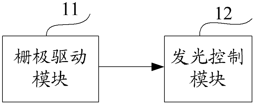
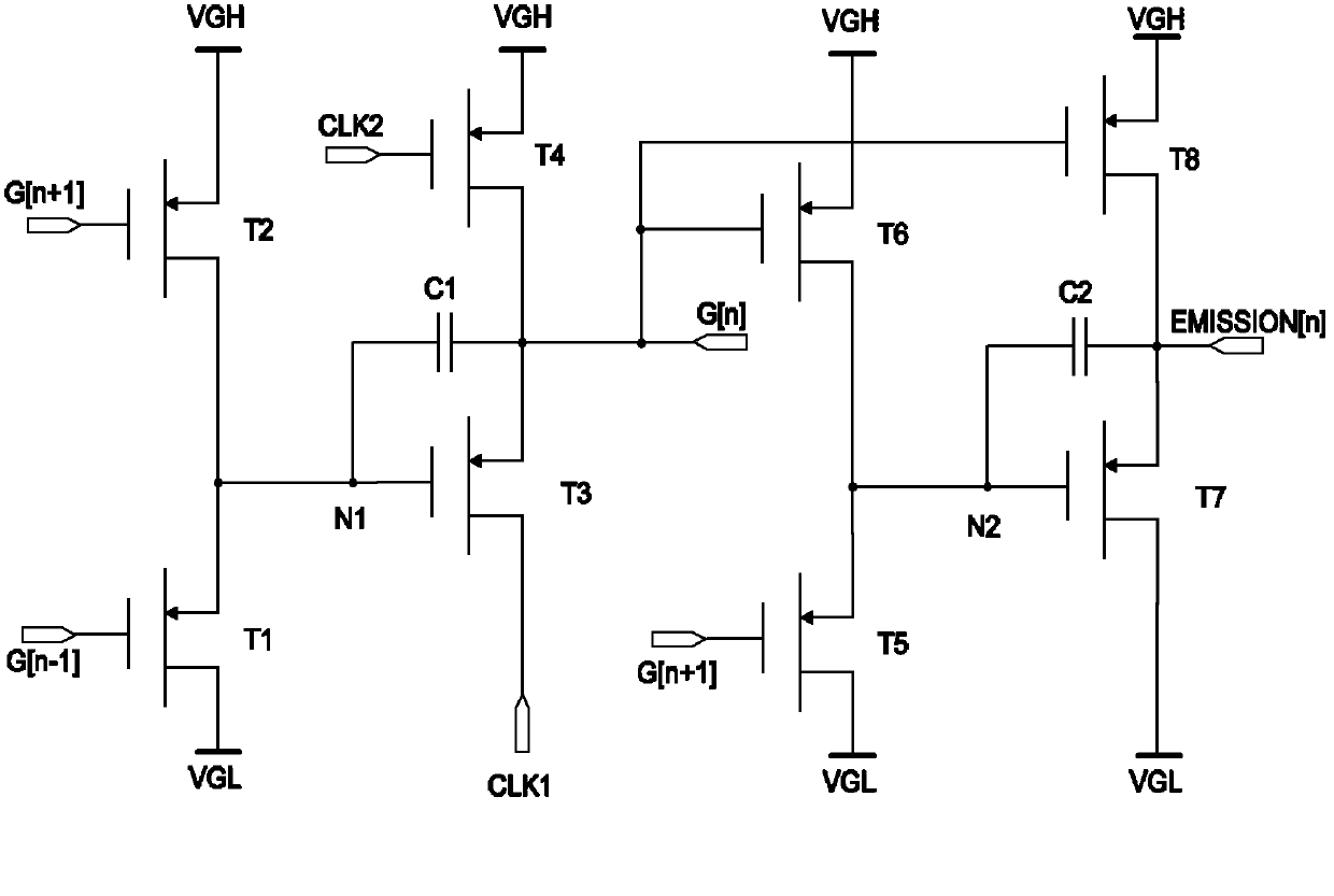
[0052]The invention provides an array substrate row drive circuit for an active matrix organic light-emitting display with simple structure and stable performance. array substrate row drive unit. Each array substrate row driving unit includes 8 thin film transistors and 2 capacitors. The row driving unit of the array substrate is divided into two stages, the first stage is used for generating conventional gate lin...


PUM


Abstract

The invention provides a gate driver on array unit, a gate driver on array circuit and a display device. The gate driver on array unit comprises a grid drive module and a light emission control module, wherein the grid drive module is used for generating grid drive signals, the light emission control module is connected with a grid drive signal output end of the grid drive module and used for generating light emission control signals for controlling an organic light-emitting diode under the control of the grid drive signals, and the grid drive signals and the light emission control signals are inverted. By the aid of the gate driver on array unit, the gate driver on array circuit and the display device, the grid drive signals can be generated while the light emission control signals inverted with the grid drive signals can be also generated to enable an OLED (organic light emitting diode) device to be at the off state in the process that display data are written into pixel cells, and after the display data are written into the pixel cells, the OLED device is turned on for light emission, so that flicker of display images due to instability of a pixel circuit during data writing is guaranteed to be avoided.

Description

technical field [0001] The invention relates to the field of organic light-emitting display, in particular to an array substrate row driving unit, an array substrate row driving circuit and a display device. Background technique [0002] Organic light-emitting display diodes (OLEDs) have been increasingly used in high-performance displays due to their advantages such as high brightness, wide viewing angle, and fast response speed. Traditional passive matrix organic light emitting display (Passive Matrix OLED) requires a shorter driving time of a single pixel as the display size increases, and thus needs to increase transient current and increase power consumption. At the same time, the application of high current will cause the voltage drop on the ITO (pixel electrode) line to be too large, and the working voltage of the OLED will be too high, thereby reducing its efficiency. The active matrix organic light-emitting display (Active Matrix OLED) can solve these problems well...

Claims


Application Information

Patent Timeline
Patent Type & Authority Applications(China)
IPC IPC(8): G09G3/32
CPCG11C19/28G09G3/32G09G3/3225G09G3/3266G09G2300/0861G09G3/20G09G3/30
Inventor 金泰逵王颖金馝奭
Owner BOE TECH GRP CO LTD
Why Eureka
Try Eureka