
Transparent display device and electronic equipment employing same

A technology of transparent display and transparent sub-pixels, applied in lighting and heating equipment, coin-operated equipment for distributing discrete items, coin-operated equipment for distributing discrete items, etc., can solve problems such as increasing the manufacturing cost of display devices, Achieving the effect of high light transmittance

Active Publication Date: 2014-11-19
HISENSE VISUAL TECH CO LTD
View PDF5 Cites 0 Cited by
  • Summary
  • Abstract
  • Description
  • Claims
  • Application Information

AI Technical Summary

Problems solved by technology

However, the addition of optical sheets and the special design of the light guide plate will increase the manufacturing cost of the display device

Method used


Image

  • Transparent display device and electronic equipment employing same
  • Transparent display device and electronic equipment employing same
  • Transparent display device and electronic equipment employing same

Examples


Embodiment Construction

[0022] In order to further explain the technical means and effects of the present invention to achieve the intended purpose of the invention, in conjunction with the accompanying drawings and preferred embodiments, the specific structure, Features and functions are described in detail below.

[0023] The aforementioned and other technical contents, features and effects of the present invention will be clearly presented in the following detailed description of the preferred embodiments with reference to the drawings. Through the description of specific embodiments, the technical means and effects of the invention to achieve the intended purpose can be understood more deeply and specifically. However, the accompanying drawings are only for reference and description, and are not used to explain the present invention. limit.

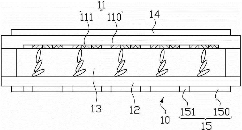
[0024] figure 1 It is a schematic structural diagram of the transparent display device in the first embodiment of the present invention. Please refer to ...


PUM


Abstract

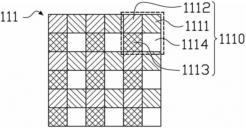
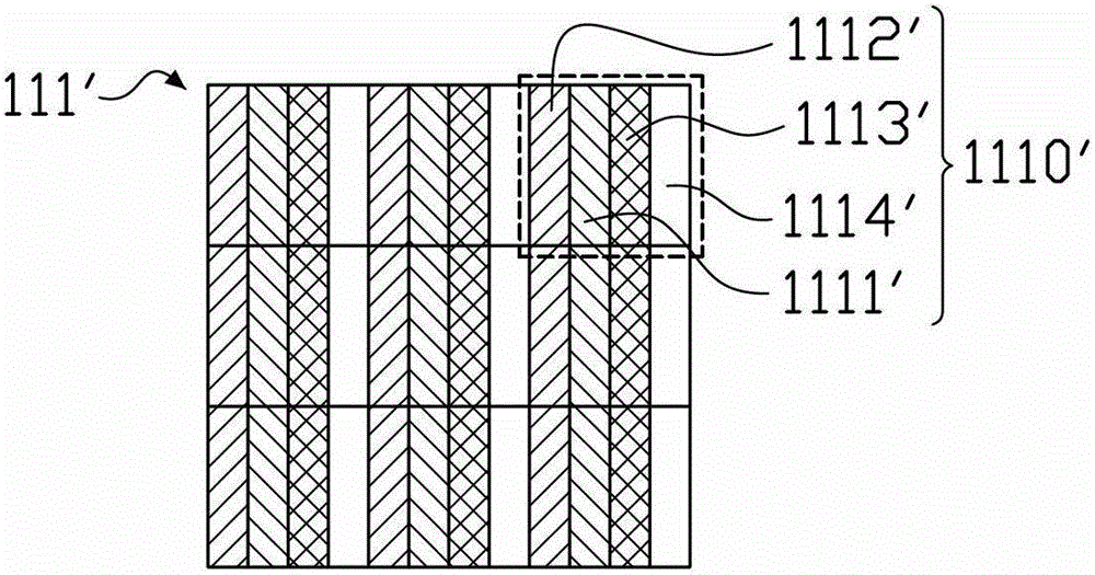
A transparent display device including a liquid crystal panel is provided. The liquid crystal panel includes a color filter substrate, an array substrate, a liquid crystal layer, a first polarizer and a second polarizer. The first polarizer is disposed on a side of the color filter substrate far from the liquid crystal layer. The second polarizer is disposed on a side of the array substrate far from the liquid crystal layer. The color filter substrate includes a transparent base, and a color filter formed on the transparent base. The color filter includes compound pixel regions, wherein each of the compound pixel regions has color sub-pixel regions and a transparent sub-pixel region. The second polarizer includes a non-polarized pattern spatially corresponding to the transparent sub-pixel region in the color filter, after a light passing through the non-polarized pattern, the polarization state remains unchanged.

Description

technical field [0001] The invention relates to the field of display technology, in particular to a transparent display device and electronic equipment with the transparent display device. Background technique [0002] Transparent display technology is an emerging display technology. This technology requires the display screen to be able to see the items placed behind it through the display screen while displaying images. This requires the display screen to maximize the light transmittance of the display screen without losing its color gamut and contrast, so that the viewer can clearly see the items behind the screen during the display process of the display screen. [0003] At the same time, transparent display technology is also a typical representative of green display technology. Take liquid crystal display panels as an example. Traditional liquid crystal display panels require a backlight module to act as a light source to display images, while transparent liquid crys...

Claims


Application Information

Patent Timeline
Patent Type & Authority Patents(China)
IPC IPC(8): G02F1/1335G02F1/13357G02F1/133G09G3/36A47F11/06A47F11/10F25D29/00G07F11/00
CPCF25D2400/36G09G2300/0456G09G3/3607G07F11/00G02F1/133528G09G3/3413G02F1/13362G02F2001/133538F25D29/00G02F1/133533G02F2001/133614G02F2201/52G02F1/133514G09G3/36G02F2203/68G02F1/133538G02F1/133614
Inventor 黄顺明
Owner HISENSE VISUAL TECH CO LTD
Learn More