
Sight synchronizing lamp

A line-of-sight and car light technology, applied in signal transmission systems, lighting and heating equipment, instruments, etc., can solve the problem that car lights cannot illuminate blind spots, and achieve the effect of avoiding danger

Inactive Publication Date: 2012-10-03
冯金勋
View PDF6 Cites 1 Cited by
  • Summary
  • Abstract
  • Description
  • Claims
  • Application Information

AI Technical Summary

Problems solved by technology

[0003] In order to overcome the situation that the existing car lights cannot illuminate the blind area, the present invention provides a line-of-sight synchronous car light, which can rotate with the direction of the driver's face to prevent entering a curve or dark areas around the vehicle, and provide a more good security

Method used


Image

  • Sight synchronizing lamp
  • Sight synchronizing lamp
  • Sight synchronizing lamp

Examples


Embodiment 1

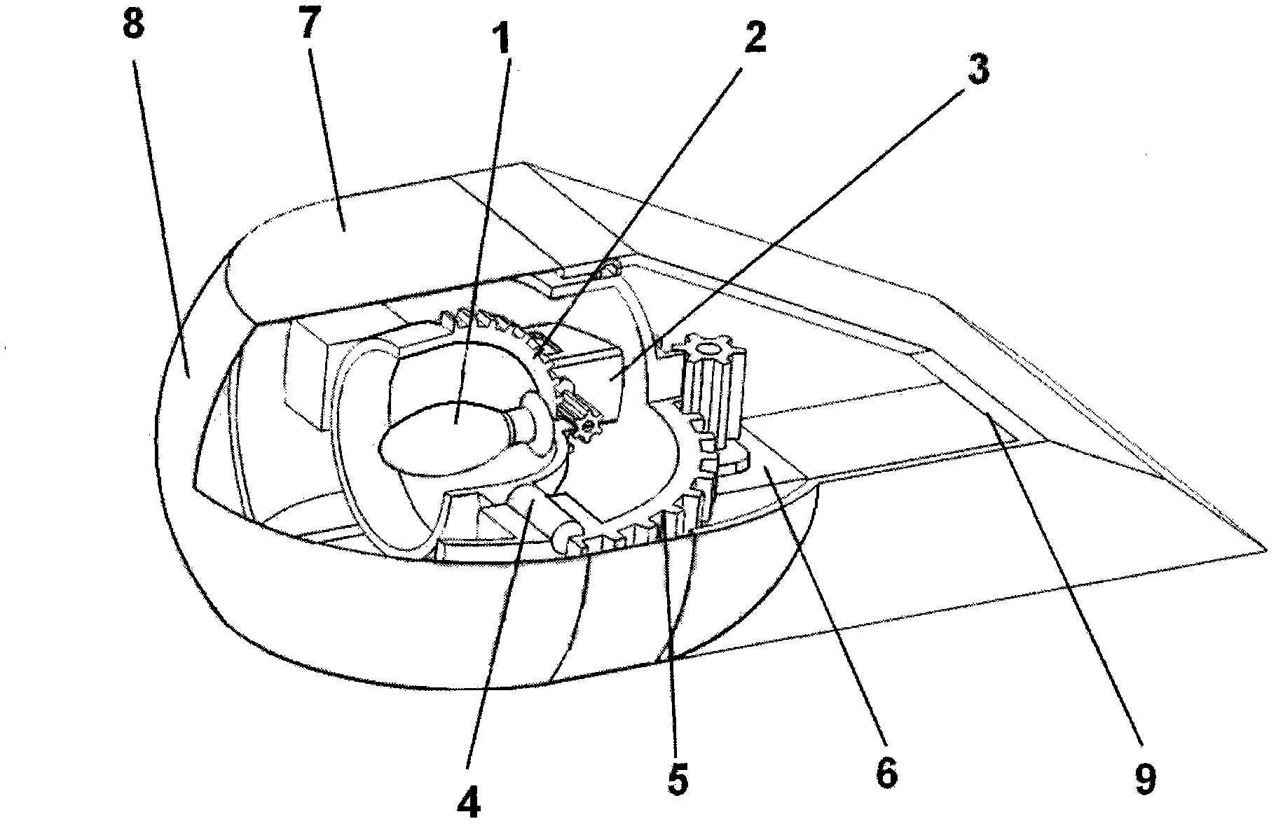
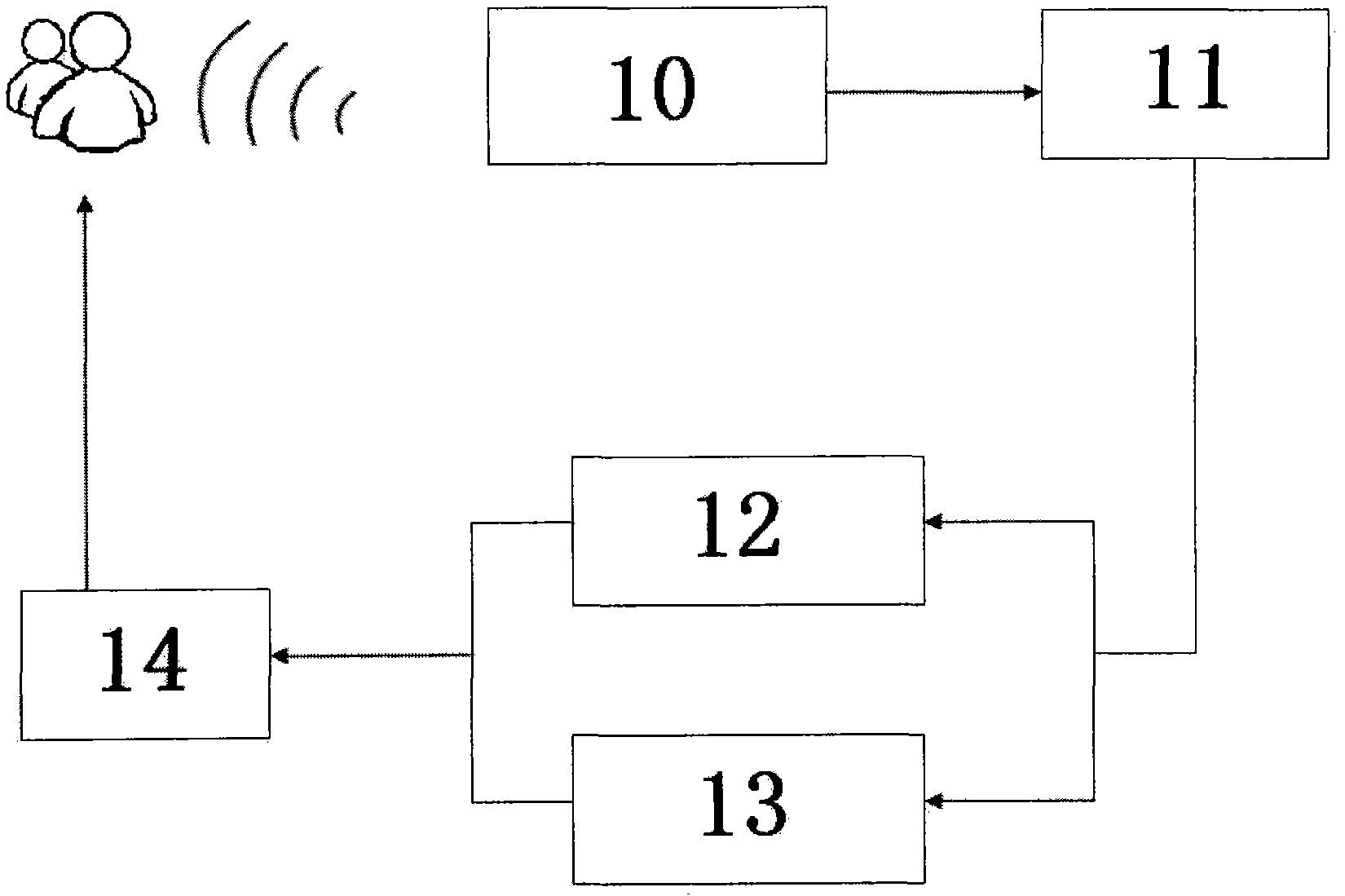
[0034] refer to figure 1 , figure 2 , to illustrate an embodiment of the present invention.

[0035] The line-of-sight synchronous lamp of the present invention is composed of a driver's face direction sensor 10, a control chip 11, a control XZ plane rotation motor 12, a control XY plane rotation motor 13, a car light part 14 and a housing for a synchronous steering light part. The driver's face is facing the sensor 10, the control chip 11, the control XZ plane rotation motor 12, the control XY plane rotation motor 13, and the car lamp part 14 are connected in sequence.

[0036] When using camera A and camera B as the driver's face direction sensor:

[0037] Place the camera A in the middle of the A-pillar on the left side of the car, facing the driver's face. Place camera B on the upper middle of the center console, facing the driver's face. The positions of camera A and camera B are not unique. In principle, they are more than 0.2 meters apart and can look directly at t...

Embodiment 2

[0050] When using three-axis gyroscope A and three-axis gyroscope B as the driver's face direction sensor.

[0051] Regarding the location of each device: the three-axis gyroscope A (located at a certain position on the head), and the rechargeable lithium battery are placed in a housing similar to the shape of ear-hook earplugs. The shape of the housing containing the three-axis gyroscope is not unique, and it is based on comfort and convenience. It can also be installed on the driver's helmet. The three-axis gyroscope B is placed somewhere in the car body, and the control chip is placed inside the center console of the car. The positions of the three-axis gyroscope B and the control chip are not unique. As long as it is inside the car body, there is no high temperature, dryness and no strong magnetic field.

[0052] The main part of the line-of-sight synchronous light composed of the shells that control the XZ plane rotation motor, control the XY plane rotation motor, the ...


PUM


Abstract

The invention relates to a sight synchronizing lamp which is capable of effectively providing good sight for a driver and solves the problem that dead zones cannot by lightened timely in the prior art. The sight synchronizing lamp comprises a driver face direction sensor and a vehicle lamp rotation following mechanism, wherein the vehicle lamp rotation following mechanism is composed of a control chip, an XZ plane rotation control motor, an XY plane rotation control motor, a vehicle lamp part and a shell of the synchronizing rotating vehicle lamp part. The sight synchronizing lamp can rotate along with the rotation direction of the face of the driver, thereby avoiding dead zones when a vehicle enters into curves or runs, and providing better safety control for the vehicle.

Description

Technical field [0001] The invention relates to a vehicle auxiliary lamp, especially for driving when the light is insufficient. Background technique [0002] At present, the existing vehicle lighting is located on the front face or roof of the car, and can only move forward or when turning with the steering wheel. When entering a curve or there is a dark area around, it is impossible to visually detect the dark area in time In this situation, it is impossible to make correct driving judgments, and dangerous situations are prone to occur. Contents of the invention [0003] In order to overcome the situation that the existing car lights cannot illuminate the blind area, the present invention provides a line-of-sight synchronous car light, which can rotate with the direction of the driver's face to prevent entering a curve or dark areas around the vehicle, and provide a more Good security. [0004] Technical scheme of the present invention is: [0005] The line-of-sight s...

Claims


Application Information

Patent Timeline
Patent Type & Authority Applications(China)
IPC IPC(8): F21S8/10F21V14/02G08C17/02F21W101/02F21W107/10
Inventor 冯金勋
Owner 冯金勋
Learn More