
Electric control type thermosistor

A thermostat, electronically controlled technology, applied in the direction of machine/engine, coolant flow control, engine components, etc., can solve the problems of wire breakage, power failure, large water resistance, low sensitivity, etc., to avoid wire breakage The effect of stable power failure, fast heating conduction, and improved sensitivity

Inactive Publication Date: 2012-10-03
曲阜天博汽车零部件制造有限公司
View PDF4 Cites 3 Cited by
  • Summary
  • Abstract
  • Description
  • Claims
  • Application Information

AI Technical Summary

Problems solved by technology

[0003] The purpose of the present invention is to provide an electronically controlled thermostat, which overcomes the problems of wax leakage, broken lead wires, power failure, excessive body volume, low sensitivity, and large water resistance in the existing structure.

Method used


Image

  • Electric control type thermosistor

Examples


Embodiment Construction

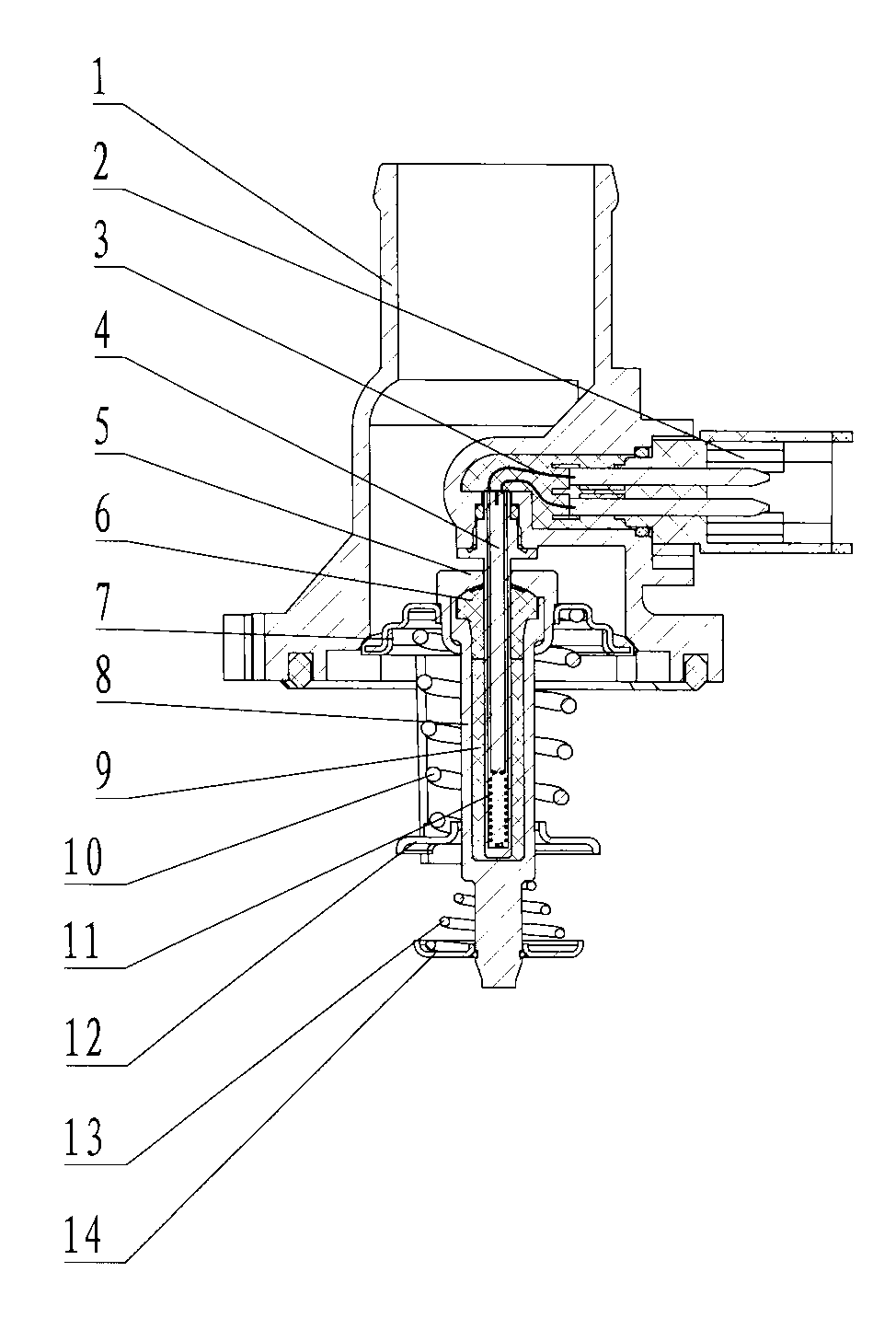
[0009] refer to figure 1 , there is a chamber 1 with two ports, a plug 2 for connecting wire 3 is arranged on one side of the chamber 1, a heated pushing mechanism with a valve 7 and a push rod 4 is installed on the chamber 1, and the heated pushing mechanism has A body 8 with a blind hole, a push rod 4 is inserted in the inner hole of the body 8, the other end of the push rod 4 protrudes outside the body 8, and a sealing ring 6 that is sealed with the opening end of the body 8 is sleeved on the push rod 4, The opening end of the body 8 is riveted to buckle the gland 5 of the sealing ring 6, and the closed space between the inner hole of the body 8 sealed by the sealing ring 6 and the push rod 4 is filled with paraffin 9, and the gland 5 is riveted to the port of the cavity 8 Corresponding to the sealed valve 7, the body 8 is covered with a spring 10 with one end pressed on the valve 7. The other end of the spring 10 is supported on the bracket 12 that guides the body 8 and is...


PUM


Abstract

The invention relates to an electric control type thermosistor which is provided with a cavity with two ports. A plug for connecting a lead is arranged at one side of the cavity; a heated pushing mechanism with a valve and a push rod is arranged on the cavity, the outer end of the push rod of the heated pushing mechanism is fixedly arranged on the cavity; a heater is arranged inside the end of the push rod positioned in the heated pushing mechanism; and the lead connected with the heater passes through an inner hole of the push rod and is connected with the plug. The electric control type thermosistor has the beneficial effects that the lead breakage power failure can be avoided, the wax leakage is avoided, the water resistance is reduced during the use, and the sensitivity is high.

Description

technical field [0001] The invention relates to an electronically controlled thermostat, which is used for cooling water circulation control of an internal combustion engine. Background technique [0002] The application prospect of electronically controlled thermostat is very broad. At present, electronically controlled thermostat is mainly composed of cavity, plug, lead wire, heater, sleeve, body, paraffin, rubber tube, push rod, spring, valve, gland, It is composed of tail handle, secondary spring and secondary valve. A hole is processed on the body, and the heater is put into the body through the hole and fixed at the bottom of the body; the heater extends out of the body through a lead wire and connects with an external plug; the push rod is in the body The hole part is covered with a rubber tube, and there is a sleeve outside the body, and the entire heating unit is fixed on the cavity through the sleeve. The heater is energized through the plug, the heater heats the ...

Claims


Application Information

Patent Timeline
IPC IPC(8): F01P7/16
Inventor 万庆江杨洪雷孔民
Owner 曲阜天博汽车零部件制造有限公司
Learn More