
Viaduct drop-off deformation seam structure and construction method of viaduct drop-off deformation seam structure

A technology of deformation joints and viaducts, which is applied to the structure of deformation joints between viaducts and drop-off platforms and its construction field, can solve problems such as unsatisfactory, and achieve the effects of ensuring waterproof and moisture-proof, reasonable structure settings, and improving road surface smoothness

Active Publication Date: 2012-10-03
BEIJING NO 3 CONSTR ENG
View PDF4 Cites 14 Cited by
  • Summary
  • Abstract
  • Description
  • Claims
  • Application Information

AI Technical Summary

Problems solved by technology

[0003] The purpose of the present invention is to provide a viaduct drop-off deformation joint structure and its construction method, to solve the problem that the traditional road surface deformation joint structure cannot satisfy the deformation of the road surface deformation joint between the viaduct and the drop-off platform in the elevated waiting hall of the railway station building

Method used


Image

  • Viaduct drop-off deformation seam structure and construction method of viaduct drop-off deformation seam structure
  • Viaduct drop-off deformation seam structure and construction method of viaduct drop-off deformation seam structure
  • Viaduct drop-off deformation seam structure and construction method of viaduct drop-off deformation seam structure

Examples


Embodiment Construction

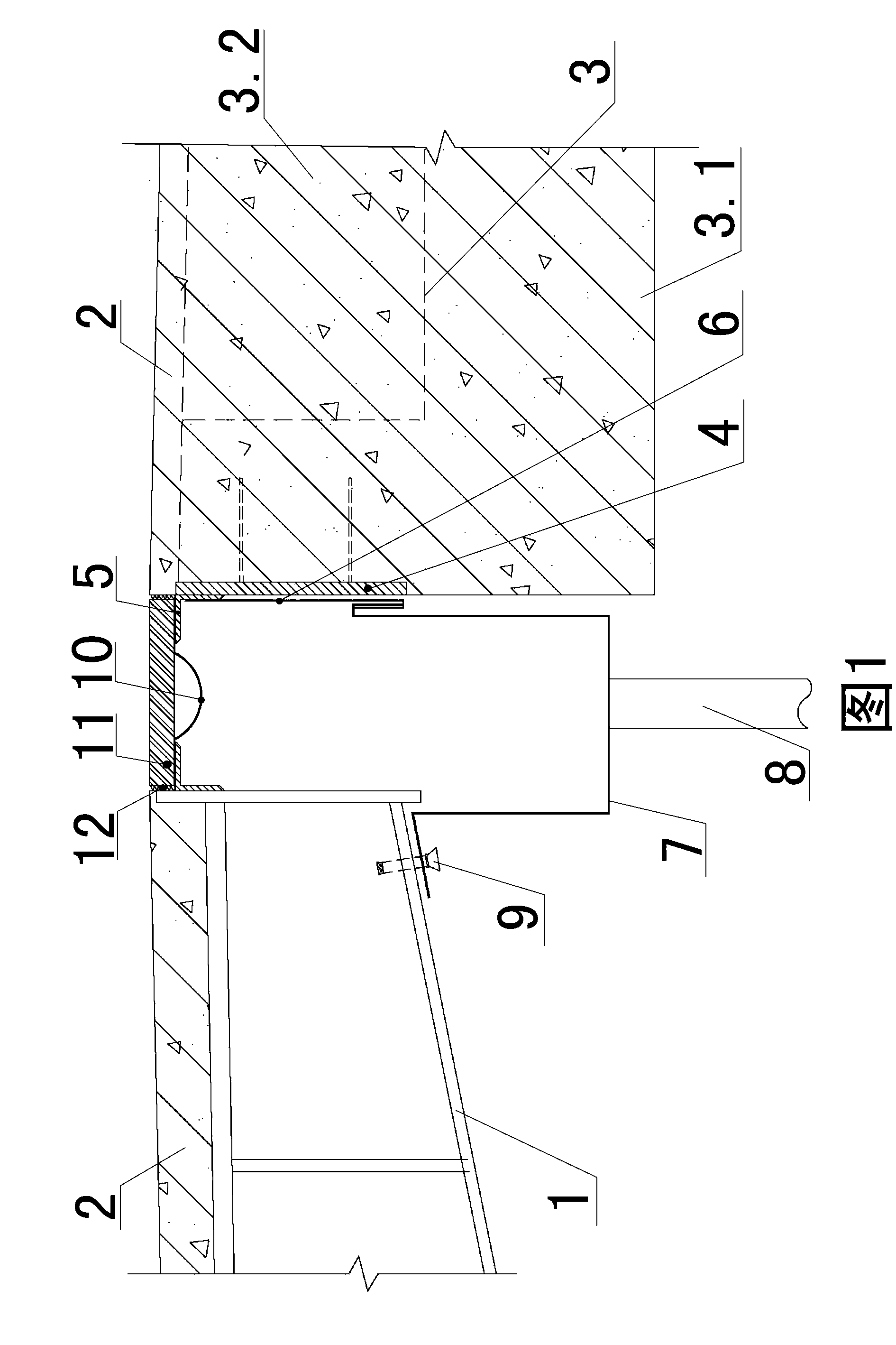
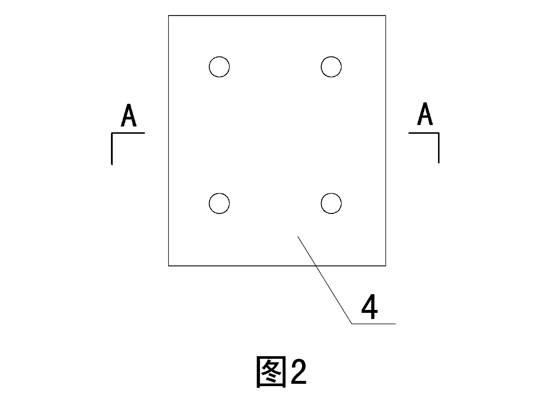
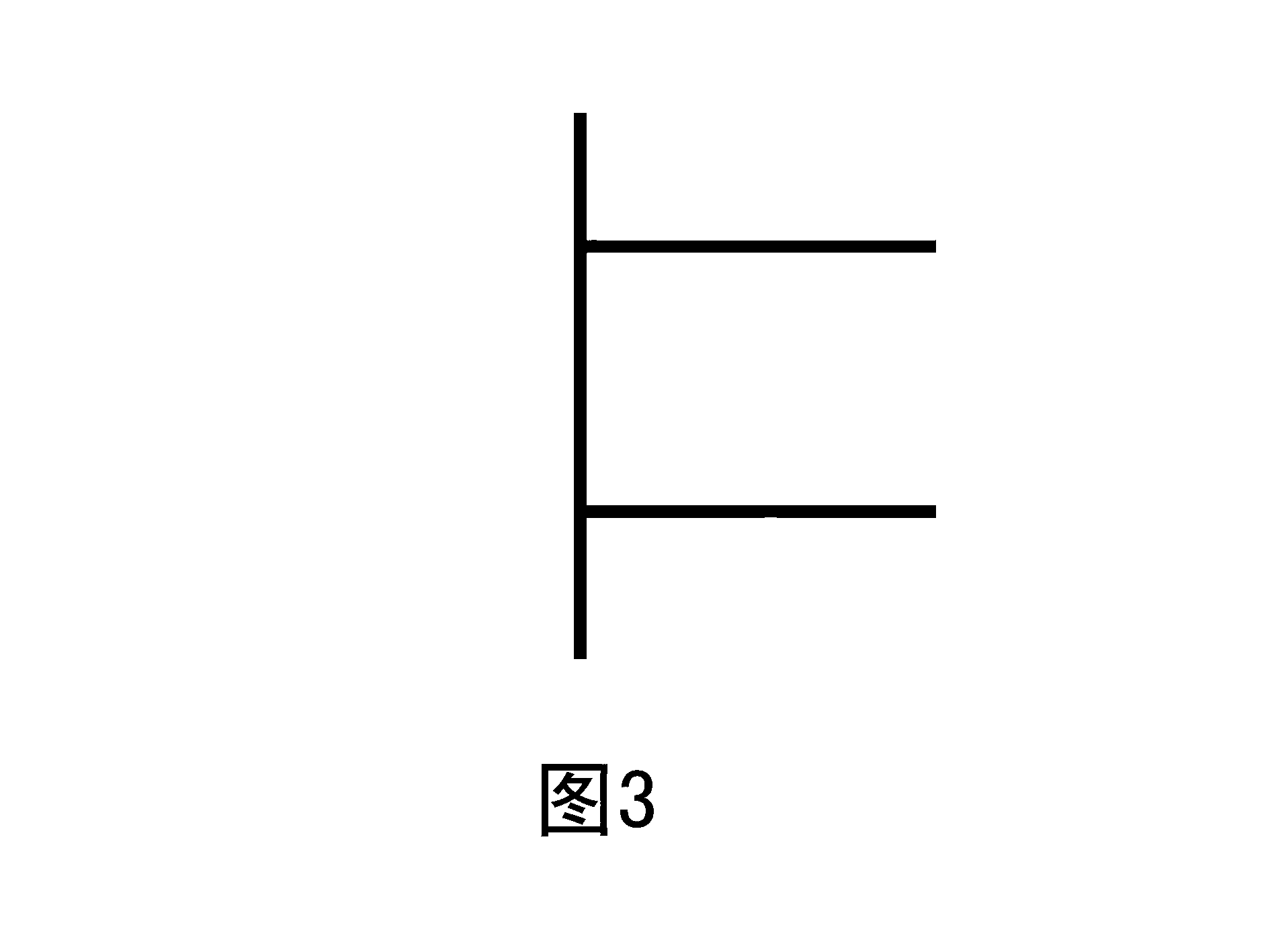
[0033] Examples see Figure 1-3 As shown, a viaduct drop-off deformation joint structure is arranged between the box-shaped steel structure 1 and the concrete structure 3, and the side of the concrete structure 3 corresponding to the box-shaped steel structure is fixed with a pre-embedded steel part 4. The upper part of the buried steel part 4 and the upper part of the box-shaped steel structure 1 are correspondingly welded with a steel support 5 facing the deformation joint, and a waterproof coiled material 10 is laid on the steel support 5 along the length direction of the deformation joint. The two sides of the waterproof coiled material 10 are placed on the steel support 5, and the middle part is suspended in the deformation joint. A steel pressing plate 11 is placed on the upper surface of the waterproof coiled material 10, and the steel pressing plate 11 covers the deformation joint. The steel pressing plate 11 Asphalt paste 12 is respectively embedded at the junction of...


PUM


Abstract

The invention relates to a viaduct drop-off deformation seam structure, which is arranged between a box type steel structure and a concrete structure, wherein one side of the concrete structure corresponding to the box type steel structure is fixedly provided with an embedded steel element, a steel support seat facing the inside of a deformation steam is correspondingly welded with the upper part of the embedded steel element and the upper part of the box type steel structure, waterproof coiled materials are paved on the steel support seat in the through length direction of the deformation seam, a steel press plate is placed on the waterproof coiled materials, and asphalt paste is respectively embedded in junction parts of the two sides of the steel press plate with the box type steel structure and the concrete structure. A groove-shaped layer board is arranged in the through length direction at the lower part of the deformation seam, one side of the groove-shaped layer board is connected with a lower wing edge of the box type steel structure, the other side of the groove-shaped layer board is fixedly connected with a hanging connecting element provided with a bent hook at the bottom end, and the upper end of the hanging connecting element is fixedly connected with the steel support seat arranged at one side of the concrete structure. The viaduct drop-off deformation seam structure solves the technical problems that the traditional pavement deformation seam structure cannot meet the requirement of various kinds of protection performance of the pavement deformation seam between a drop-off platform and a viaduct of a railway station building viaduct waiting hall under the deformation condition.

Description

technical field [0001] The invention relates to a structure of a deformation joint on a building floor and a construction method thereof, in particular to a structure of a deformation joint between a viaduct and a drop-off platform and a construction method thereof. Background technique [0002] The elevated waiting hall of the railway station building is generally located above the platform and the train track, and the viaduct that passengers pass to the elevated waiting hall of the station is connected to the drop-off platform. In order to eliminate the cracking and uplift of the road surface caused by structural deformation and improve the smoothness of the road surface and driving comfort, deformation joints should be set between the viaduct and the drop-off platform. The viaduct is a box-section steel structure, and the drop-off platform is a concrete beam-slab structure , the asphalt concrete pavement of the bridge deck is laid on the deformation joint between two diff...

Claims


Application Information

Patent Timeline
Patent Type & Authority Applications(China)
IPC IPC(8): E01D19/06E01D19/08E01D21/00
Inventor 柳沁陈硕晖郭彦玉韩涛陈默赵文轶
Owner BEIJING NO 3 CONSTR ENG
Learn More