Adjustable light spot intercepting device and method thereof

An adjustable and light spot technology, applied in the laser field, can solve problems such as inconvenient operation and affecting beam quality, and achieve a wide range of applications

Inactive Publication Date: 2014-08-27
BEIJING GK LASER TECH
View PDF3 Cites 0 Cited by
  • Summary
  • Abstract
  • Description
  • Claims
  • Application Information

AI Technical Summary

Problems solved by technology

[0003] 1. After the spot passes through the aperture, there will be modulation inside, which affects the beam quality (such as figure 2 shown)
[0004] 2. If you want to adjust the shape and size of the aperture, you have to replace the aperture with a new one, which is very inconvenient to operate

Method used


Image

  • Adjustable light spot intercepting device and method thereof
  • Adjustable light spot intercepting device and method thereof
  • Adjustable light spot intercepting device and method thereof

Examples


Embodiment Construction

[0035] The present invention will be further described below in conjunction with the accompanying drawings and specific embodiments.

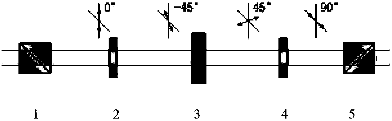
[0036] image 3 shows the optical path of the adjustable spot intercepting device according to an embodiment of the present invention, refer to image 3 , the adjustable spot intercepting device includes a polarization beam splitter 1 (Polarization Cube Beamsplitter, abbreviated as PBS), a left-handed 45° rotor 2, a liquid crystal spatial light modulator 3, a right-handed 45° rotor 4 and a polarization Dichroic prism 5.

[0037] In this embodiment, the first PBS acts as a polarizer (it is easy to understand that the PBS can also be replaced by a polarizer), which makes the polarization state of the light level. The left-handed 45° rotor rotates the light with a horizontal polarization state by 45° to the left, so that the polarization state of the light is 45° to the long axis of the liquid crystal molecules of the liquid crystal spatial ligh...


PUM


Abstract

The invention provides an adjustable light spot intercepting device which comprises a light switch array. The light switch array controls on and off of various pixels by an inputted binary image, the middle of the binary image is a bright pixel so that a light transmitting window is formed on the light switch away, a transitional strap is arranged on the edge of the binary image, the density of bright pixels in the transitional strap is gradually reduced to the minimum from the maximum, and the density of dark pixels in the transitional strap is gradually increased to the maximum from the minimum. Internal modulation of light spots can be avoided; the shapes and the sizes of the intercepted light spots are adjusted conveniently; and the array of light switches such as a DMD (digital micromirror device) can be used for intercepting the light spots, and an application scope is wide.

Description

technical field [0001] The present invention relates to the field of laser technology, in particular, the present invention relates to an adjustable light spot interception device and method. Background technique [0002] In the prior art, a diaphragm is generally used in the laser light path to intercept the light spot, so as to limit the shape of the light spot propagating in the subsequent light path. Existing diaphragms are generally made of metal materials, and typical diaphragm structures are as follows: figure 1 As shown, the shape of the small hole is determined according to the needs, such as rectangle or circle. However, when the existing aperture is used to intercept the light spot, there are the following disadvantages: [0003] 1. After the spot passes through the aperture, there will be modulation inside, which affects the beam quality (such as figure 2 shown). [0004] 2. If you want to adjust the shape and size of the aperture, you have to replace the ap...

Claims


Application Information

Patent Timeline
Patent Type & Authority Patents(China)
IPC IPC(8): G02B27/09G02B27/28G02F1/13
Inventor 邱基斯樊仲维唐熊忻
Owner BEIJING GK LASER TECH
Why Eureka
Try Eureka