Eureka AIR delivers breakthrough ideas for toughest innovation challenges, trusted by R&D personnel around the world.

Three-in-one sealed flexible core setting fixture

A three-in-one, flexible technology, applied in the direction of manufacturing tools, molding machine parts, casting and molding equipment, etc., can solve the problems of uneven thickness of the workpiece, high labor intensity of core setting, and difficulty in user maintenance, etc., to achieve reduction The effect of inaccurate positioning, improving the range of use, and compensating for shape and position errors

Inactive Publication Date: 2012-09-26
CHANGSHA CTR ROBOTICS
View PDF8 Cites 13 Cited by
  • Summary
  • Abstract
  • Description
  • Claims
  • Application Information

AI Technical Summary

Problems solved by technology

Manual placement of sand cores is inaccurate, the thickness of the produced workpieces is not very uniform, and there will be hidden dangers in the quality of the products produced; at the same time, the work of setting the cores is labor-intensive and the working environment is harsh, which is harmful to the health of workers.
In the foundry industry, the design requirements of the core fixture are very strict. If the design is unreasonable, due to the error of the workpiece itself, it will not be able to clamp or the sand core will be damaged.
The dust-proof effect of the fixture itself in the prior art is poor, and the replacement of wearing parts is relatively frequent
Since multiple products are often produced on the same production line, fixtures need to be replaced continuously. If the positioning is inaccurate due to the replacement of fixtures, it will cause difficulties for users to use and maintain.

Method used


Image

  • Three-in-one sealed flexible core setting fixture
  • Three-in-one sealed flexible core setting fixture
  • Three-in-one sealed flexible core setting fixture

Examples


Embodiment Construction

[0023] The present invention will be described in detail below in conjunction with the embodiments and accompanying drawings.

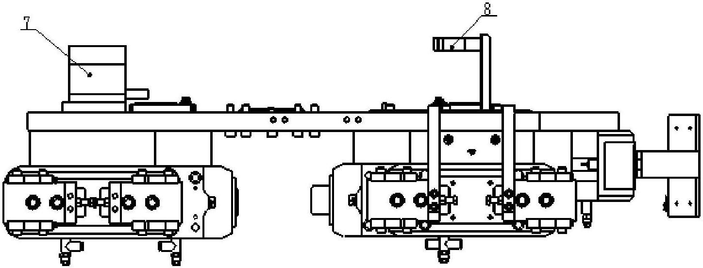
[0024] Such as figure 1 As shown: 5 sets of fixture devices are set on the main body mounting plate 1, which are fixed jaws 2 of the bolster sand core fixture mechanism, flexible jaw 3 of the bolster sand core fixture mechanism, square frame sand core fixture mechanism 4, and side frames Sand core fixture mechanism fixed jaw 5, side frame sand core fixture mechanism flexible jaw 6, air control unit 7, cable mounting frame 8.

[0025] Such as figure 2 , image 3 , Figure 4 Shown: bolster sand core fixture mechanism fixed jaw 2, bolster sand core fixture mechanism flexible jaw 3 is the jaw of bolster sand core, bolster sand core fixture mechanism fixed jaw 2, bolster sand core The air claws provided by the flexible jaws 3 of the fixture mechanism are all air claws I204. The two air grippers I 204 are respectively fixed to the mounting plate 205 a...


PUM


Abstract

The invention discloses a three-in-one sealed flexible core setting fixture, which is formed by combining three sets of fixtures, e.g., a swing bolster sand core fixture, a side frame sand core fixture and a box sand core fixture, wherein each of the swing bolster sand core fixture and the side frame sand core fixture consists of two sets of pneumatic clamping jaws, and a clamping structural form is that one set of pneumatic clamping jaw is fixed, and the other set of pneumatic clamping jaw is a flexible mechanism; and the flexible mechanism has a sealed structure, positive pressure is generated for dust prevention in the sealed structure, and the top of the sealed structure is oiled and lubricated. Compared with a fixture with the conventional structure, the swing bolster sand core fixture adopting the structure of clamping the positions of reinforcing ribs is more stable in clamping; and due to the adoption of internal clamping, a movable block required by the conventional external clamping is eliminated during the sand core manufacture of a customer to lower the sand core manufacture cost of the customer. By a mounting mode for abrasion-proof cushions of the side frame sand core fixture and the box sand core fixture, frictional contact areas are enlarged, the abrasion-proof cushions can be more firmly arranged, and the fixture can more stably and reliably work.

Description

technical field [0001] The invention belongs to casting equipment, and is a three-in-one sealed and flexible core lowering fixture. Background technique [0002] At present, there are relatively few flexible core laying equipment, and manual labor occupies a large proportion. Manually placing the sand cores is inaccurately placed, and the thickness of the produced workpieces is not very uniform, and there will be hidden dangers in the quality of the produced products. At the same time, the work of setting the cores is labor-intensive and the working environment is harsh, which is harmful to the health of workers. In the foundry industry, the design requirements of the core fixture are very strict. If the design is unreasonable, due to the error of the workpiece itself, it will not be able to clamp or the sand core will be damaged. The dust-proof effect of the fixture itself in the prior art is relatively poor, and the wearing parts are replaced relatively frequently. Since...

Claims


Application Information

Patent Timeline
IPC IPC(8): B22C19/00B22D29/00
Inventor 徐岩张峰高金锐徐长辉崔世海杨靖玉
Owner CHANGSHA CTR ROBOTICS
Why Eureka
Eureka Blog
Learn More