Sliding mounting method for large-sized transformer

A technology of transformer and sliding method, which is applied in the direction of transformer/reactor installation/support/suspension, switchgear, electrical components, etc., and can solve the problems of large-scale hoisting equipment and many construction workers.

Inactive Publication Date: 2012-09-19
CHINA MCC17 GRP
View PDF5 Cites 19 Cited by
  • Summary
  • Abstract
  • Description
  • Claims
  • Application Information

AI Technical Summary

Problems solved by technology

Consuming large hoisting equipment, the shift is relatively large, and the construction personnel are relatively large

Method used


Image

  • Sliding mounting method for large-sized transformer
  • Sliding mounting method for large-sized transformer
  • Sliding mounting method for large-sized transformer

Examples


Embodiment approach

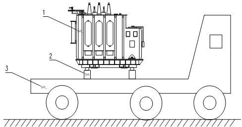
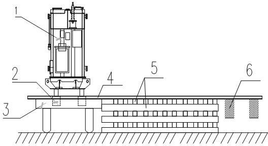
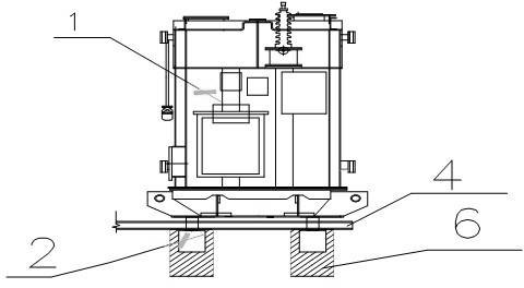
[0018] Such as figure 1 , 2 , Shown in 3, 4, large-scale transformer sliding method of the present invention comprises oil pumping station, hydraulic jack, heavy object on-rail type pushing machine, track, sleeper, transformer. After the transformer is transported in place, sleepers are laid in advance, the transformer is jacked up, then inserted into the rail, and the transformer is pushed to the installation position in the center of the foundation by using the on-rail pusher.

[0019] From figure 1 It can be seen that when the transformer 1 is loaded and transported, it is necessary to ensure that there is a certain reserved space at the bottom of the transformer to facilitate the placement of four hydraulic jacks 2 for lifting work, and the parking position of the transport vehicle 3 must be determined to ensure that the transformer can slide horizontally direction.

[0020] During the jacking process, the four hydraulic jacks 2 must be synchronized, the transformer 1...


PUM


Abstract

The invention discloses a sliding method for a large-sized transformer. An oil pump station, hydraulic jacks, a heavy object on-rail pusher, a rail, sleepers and the transformer are involved. The method specifically comprises the following working steps that: after the transformer is transported to a proper position, the sleepers are laid in advance, the transformer is jacked, the steel rail is inserted, and the transformer is pushed to a mounting position in the center of a foundation by utilizing the on-rail pusher. By the method, large-sized hoisting equipment machine teams, manpower and materials can be reduced, the transformer can be easily and conveniently mounted, and the method is low in labor intensity and high in safety.

Description

technical field [0001] The invention belongs to the technical field of electrical equipment installation, and in particular relates to a convenient method for unloading, sliding and installing a transformer. Background technique [0002] With the rapid development of my country's industry, a large number of substations matching the production workshops are correspondingly required. In the installation process of electrical equipment in the industrial industry, large transformers are often installed in the transformer room. Due to the large size and heavy weight of large transformers, the installation requirements are high. At present, the transformer installation method is usually based on the weight of the transformer, the site, the installation location, etc., select the corresponding crane to unload, move to the transformer door, and push or pull the slip on the track that has been set. This method requires technicians to accurately calculate the lifting weight, crane pa...

Claims


Application Information

Patent Timeline
Patent Type & Authority Applications(China)
IPC IPC(8): H01F27/06H02B3/00
Inventor 张晓波
Owner CHINA MCC17 GRP
Why Eureka
Try Eureka