
Device for detecting defects and laser induced damages of optical material

A detection device and technology of optical materials, applied in the field of optical detection, can solve the problems of inability to intuitively reflect photo-induced damage and increase the complexity of detection

Inactive Publication Date: 2012-09-19
SHANGHAI INST OF OPTICS & FINE MECHANICS CHINESE ACAD OF SCI
View PDF3 Cites 21 Cited by
  • Summary
  • Abstract
  • Description
  • Claims
  • Application Information

AI Technical Summary

Problems solved by technology

This method cannot intuitively reflect the microscopic photodamage, and the detection of the photodamaged area requires multiple operations, which also increases the complexity of the detection

Method used


Image

  • Device for detecting defects and laser induced damages of optical material
  • Device for detecting defects and laser induced damages of optical material
  • Device for detecting defects and laser induced damages of optical material

Examples


Embodiment Construction

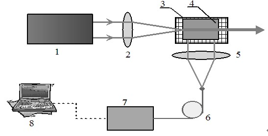
[0022] see figure 1 , figure 1 It is a structural schematic diagram of the optical material defect and photo-induced damage detection device of the present invention. As can be seen from the figure, the detection device for defects and photoinduced damage of optical materials of the present invention is composed of a laser 1, a focusing lens 2, an optical sample to be measured 4, an object stage 3, an imaging lens 5, an optical fiber 6, a grating spectrometer 7 and a computer 8 , the positional relationship of the above components is as follows:

[0023] The probe beam output by the laser 1 is focused by the focusing lens 2, and then incident on the optical sample 4 to be tested placed on the stage 3, and the fluorescence signal generated by the laser excitation of the optical sample 4 to be tested passes through the imaging lens 5 and then is guided by the optical fiber 6 into the optical sample 4. The above-mentioned grating spectrometer 7, the spectrum and fluorescence in...


PUM

PropertyMeasurementUnit
wavelengthaaaaaaaaaa

Abstract

The invention relates to a device for detecting defects and laser induced damages of an optical material, which is composed of a laser, a focusing lens, a to-be-detected optical sample, an object stable, an imaging lens, an optical fiber, a grating spectrometer and a computer, wherein fluorescent spectrum information generated by the to-be-detected optical sample in a laser irradiation manner is detected and analyzed, so that optical transparency of different types of the optical materials at a special working wavelength can be analyzed and judged; in addition, laser induced damage conditions of the to-be-detected sample can be analyzed and judged. According to the device, the optical material applied to a special laser wavelength can be selected, and the laser induced damages of the material caused by strong laser irradiation can be detected online.

Description

technical field [0001] The invention belongs to optical detection, in particular to a detection device for defects and light-induced damage of optical materials. Background technique [0002] Fused silica and calcium fluoride are the main materials for optical components in excimer laser cavities and optical components in large-scale laser nuclear fusion devices. The defect centers of optical materials will cause optical absorption, which will affect the transmittance of optical components, and even produce instantaneous or permanent optical damage under the action of high-energy-density lasers, which will reduce the transmittance of optical components or system efficiency. In order to judge and select the suitable high-transmittance optical material in the laser cavity, and quickly detect the degree of photo-induced damage of the optical element modulated by the laser, so as to provide a reference for repairing the damaged element. Therefore, the detection of laser-induced...

Claims


Application Information

Patent Timeline
Patent Type & Authority Applications(China)
IPC IPC(8): G01N21/64
Inventor 张海波袁志军周军楼祺洪魏运荣何兵漆云凤杜松涛
Owner SHANGHAI INST OF OPTICS & FINE MECHANICS CHINESE ACAD OF SCI
Learn More