Primary-secondary ejector
An ejector and mother-child technology, which is applied in the field of two-fluid mixed-flow components, can solve the problems that large-flow ejectors are not suitable, the structure is complex and special, and the axial size and weight are reduced, and the work-hour performance is good. The effect of strong fluid capacity
- Summary
- Abstract
- Description
- Claims
- Application Information
AI Technical Summary
Problems solved by technology
Method used
Image
Examples
Embodiment 1
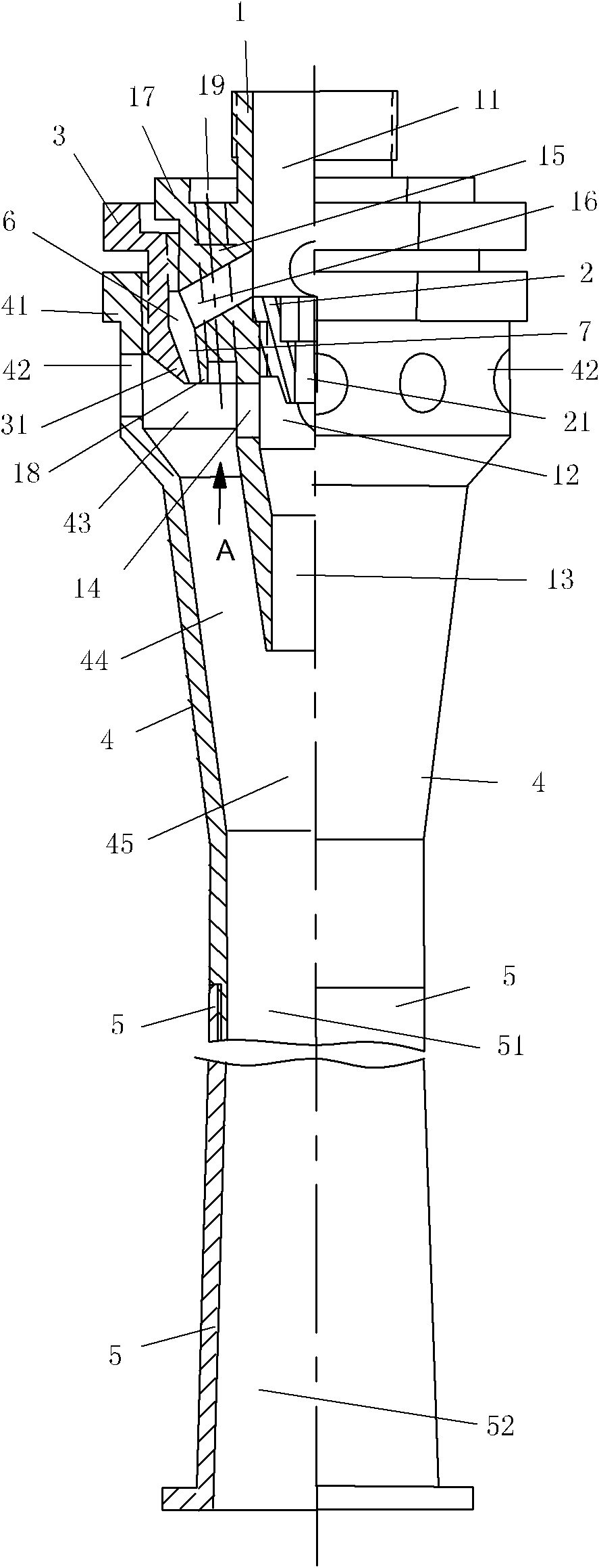
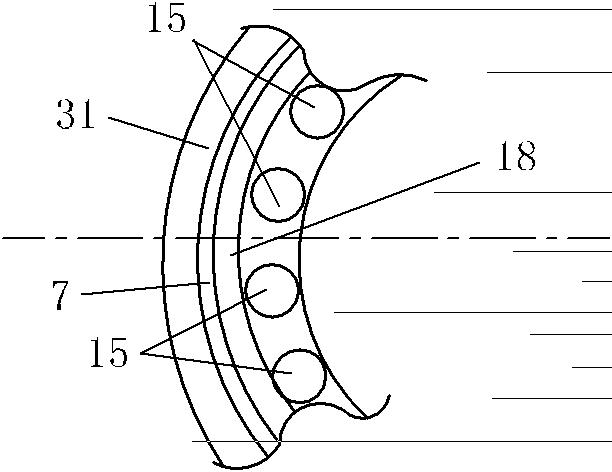
[0034] The structure of the first embodiment of the parent-child ejector of the present invention, such as figure 1 as shown, figure 1 The upper part is the actual front, and the lower part is the actual rear. The sub-female ejector consists of a short inner tube 1, a central nozzle 2, a connecting sleeve 3, a long and thick outer tube 4 and an annular nozzle 7. The inner pipe 1 and the central nozzle 2 form the central ejector, and the inner pipe 1, the outer pipe 4, the connecting sleeve 3 and the annular nozzle 7 form the annular ejector. The input end of the central ejector is coaxially fixed in the inlet of the diameter-expanding section 41 of the input end of the annular ejector, and the middle and rear sections of the central ejector are coaxially suspended in the annular ejector. The middle and rear sections of the outer tube 4, which are axially longer than the outlet of the inner tube 1, constitute the total mixing output pipe. The inner cavity of the inlet section...
Embodiment 2
[0047] The structure of the second embodiment of the parent-child ejector of the present invention, as Figure 5 shown. Figure 5 The upper part is the actual front, and the lower part is the actual rear. The mother-child ejector consists of a short and small inner tube 10, a central nozzle 20, a connecting sleeve 30, and a thick and long outer tube 40. The inner tube 10 and the central nozzle 20 constitute a central ejector. The inner tube 10, the connecting sleeve 30 and the outer tube 40 form an annular injector. The central ejector is coaxially arranged in the annular ejector, and the outlets of the central ejector and the annular ejector communicate with the main mixing chamber 450 and the main mixing pipe 460 .
[0048]The front portion of the inner tube 10 is a large diameter straight circle central hole, and the middle part is an enlarged diameter hole section made up of the largest diameter straight hole section and the backward shrinkage cone, after the enlarged d...
Embodiment 3
[0063] see Figure 8 , the structure of this embodiment is basically the same as that of Embodiment 2. Figure 8 The upper part is the actual front, and the lower part is the actual rear. The female ejector consists of a short inner tube 100 , a central nozzle 200 , a connecting sleeve 300 and a long and thick outer tube 400 . The inner pipe 100 and the central nozzle 200 form the central ejector, and the inner pipe 100, the outer pipe 400 and the connecting sleeve 300 form the annular ejector. The input end of the central ejector is coaxially fixed in the inlet of the expanding section of the input end of the annular ejector, and the middle and rear sections of the central ejector are coaxially suspended in the annular ejector. The outer tube 400 is axially longer than the inner tube 100. The middle and rear section of the outlet end constitutes the total mixing output pipe. The inner cavity of the inlet section of the total mixing output tube is the total mixing chamber 45...
PUM
 Abstract
Description
Claims
Application Information
 - R&D Engineer
- R&D Manager
- IP Professional
- Industry Leading Data Capabilities
- Powerful AI technology
- Patent DNA Extraction
Browse by: Latest US Patents, China's latest patents, Technical Efficacy Thesaurus, Application Domain, Technology Topic, Popular Technical Reports.
© 2024 PatSnap. All rights reserved.Legal|Privacy policy|Modern Slavery Act Transparency Statement|Sitemap|About US| Contact US: help@patsnap.com


