
U-shaped aqueduct simulation testing device and method

A test device and aqueduct technology, which is applied to hydraulic models and other directions, can solve the problems that the combined steel mold in the test section can only be used once and be scrapped, takes a lot of time, and wastes a lot of time, so as to save labor, time, safety, economy, and economy. Effective, low-cost effect

Active Publication Date: 2014-08-20
CHINA GEZHOUBA GROUP CO LTD +1
View PDF5 Cites 0 Cited by
  • Summary
  • Abstract
  • Description
  • Claims
  • Application Information

AI Technical Summary

Problems solved by technology

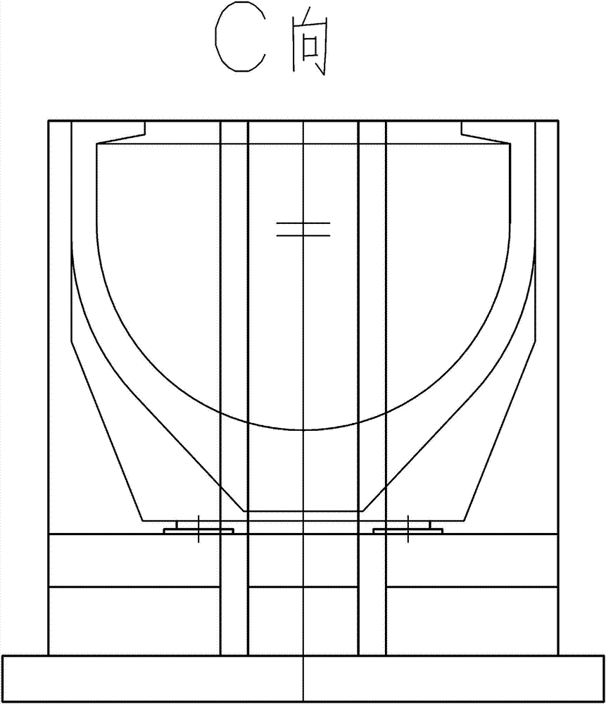
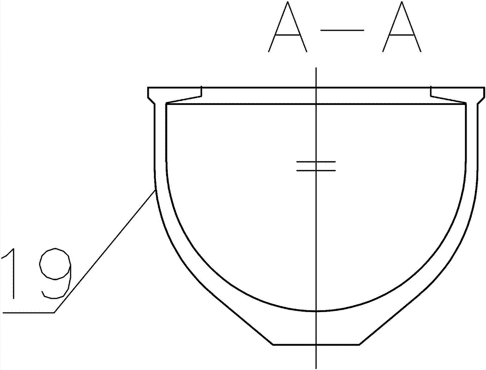
[0004] The structure of the aqueduct simulation test is as follows: Figure 1-4 As shown, the aqueduct structure of the test section is the same as the aqueduct structure of the main project. The calculated weight of the single-span aqueduct body concrete is about 1600 tons (including 17 reinforced concrete prefabricated tension beams weighing about 95 tons, steel bars weighing about 100 tons, and steel hinges weighing about 35 tons), the concrete volume is about 640 cubic meters, the estimated weight of the combined internal and external steel formwork is 400 tons, and the combined weight exceeds 2,000 tons. Assuming that the pier at both ends of the aqueduct bears 250 tons each, the remaining 1,500 tons will be borne by the external formwork mechanism. To pour this cross-simulation test tank body, it is necessary to have a set of combined steel molds, and to design and process a set of combined steel molds for the aqueduct body in the simulation test section. It takes a lot of time, and the combined steel mold in the test section can only be used once and then scrapped, which is uneconomical and wastes a lot

Method used


Image

  • U-shaped aqueduct simulation testing device and method
  • U-shaped aqueduct simulation testing device and method
  • U-shaped aqueduct simulation testing device and method

Examples


Embodiment Construction

[0048] Such as Figure 1-4 In the test section 1:1 simulation test, the length of the aqueduct body 19 is 40m, and the dimensions of the inner space are 40.0m×9.0m×7.23m. The wall aqueduct and U-shaped aqueduct have a wall thickness of 350 mm and a weight of 1,600 tons. The first pier 1 and the second pier 4 are arranged at both ends of the tank body 19, and there are heads 22 on both sides. Beam 20.

[0049] Such as Figure 7 Among them, a U-shaped aqueduct simulation test device includes an outer mold 14 and an inner mold system. In the inner mold system, the inner mold 11 is movably suspended on a part of the inner beam 9 located in the outer mold 14,

[0050] Located outside one end of the outer mold 14, a plurality of track buttresses 5 are arranged, and on the track buttresses 5, track combined steel beams 6 are installed, and on the track combined steel beams 6, inner mold installation tracks 7 are installed;

[0051] The inner beam 9 is supported by the first leg 8 ,...


PUM


Abstract

A U-shaped aqueduct simulation testing device comprises an outer mould system and an inner mould system. In the inner mould system, an inner mould is movably hung on inner beams, one part of the inner beams are arranged in outer moulds, a plurality of track buttresses are arranged on the outer sides of one ends of the outer moulds, and track combination steel beams are arranged on the track buttresses and provided with inner mould installation tracks; the inner beams are supported by a first support leg, a second support leg, a third support leg and a fourth support leg; portal beams are connected with the upper ends of outer ribs through vertical adjusting draw bars, a transverse draw rod is respectively arranged between each two openings of the outer rib, and a square wood support body and a support unloading device are arranged between a flat section bottom and a base buttress below the outer ribs; and the outer moulds are installed in U-shaped space of a plurality of the outer ribs. According to the U-shaped aqueduct simulation testing device, large-scale aqueduct simulation testing pouring can be achieved, the technical problem of the combined steel mould construction of aqueduct simulation tests is solved, by means of the outer mould system and the inner mould system of an aqueduct producing machine, large-scale aqueduct simulation tests are achieved by using low costs.

Description

technical field [0001] The invention relates to the construction field of large-scale U-shaped aqueducts in water conservancy projects, in particular to a U-shaped aqueduct simulation test device and method for obtaining relevant data in the field of large-scale aqueducts lacking existing empirical data. The invention can also be practically used in the construction of large-scale aqueducts in water conservancy projects. Background technique [0002] The aqueduct of a water conservancy project is a three-channel prestressed concrete U-shaped structure independent of each other, with a total of 18 spans and a total of 54 sections of aqueduct. m, U-shaped aqueduct with a wall thickness of 350mm is a post-tensioned three-way prestressed thin-walled aqueduct, and 17 reinforced concrete tension beams are designed on the upper part of the aqueduct. The total weight of the aqueduct is 1600 tons, about 640 cubic meters of concrete. Due to the length and size of the single span of ...

Claims


Application Information

Patent Timeline
Patent Type & Authority Patents(China)
IPC IPC(8): E02B1/02
Inventor 吴平安郭灵敏赵志忠冯洪彬崔志成方勇
Owner CHINA GEZHOUBA GROUP CO LTD
Learn More