Concrete breaker

A technology of concrete and crushers, applied in roads, road repairs, roads, etc., can solve problems that affect the smoothness of roads and take a long time, and achieve the effect of convenient operation process

Inactive Publication Date: 2012-09-19
朱奎
View PDF0 Cites 6 Cited by
  • Summary
  • Abstract
  • Description
  • Claims
  • Application Information

AI Technical Summary

Problems solved by technology

However, this repair method takes a long time, especially the smashing and excavation of concrete slag are generally done manually, which is likely to affect the smooth flow of the road

Method used


Image

  • Concrete breaker
  • Concrete breaker

Examples


Embodiment Construction

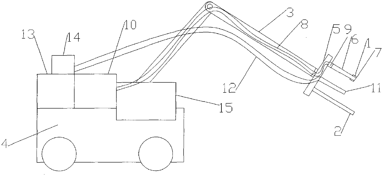
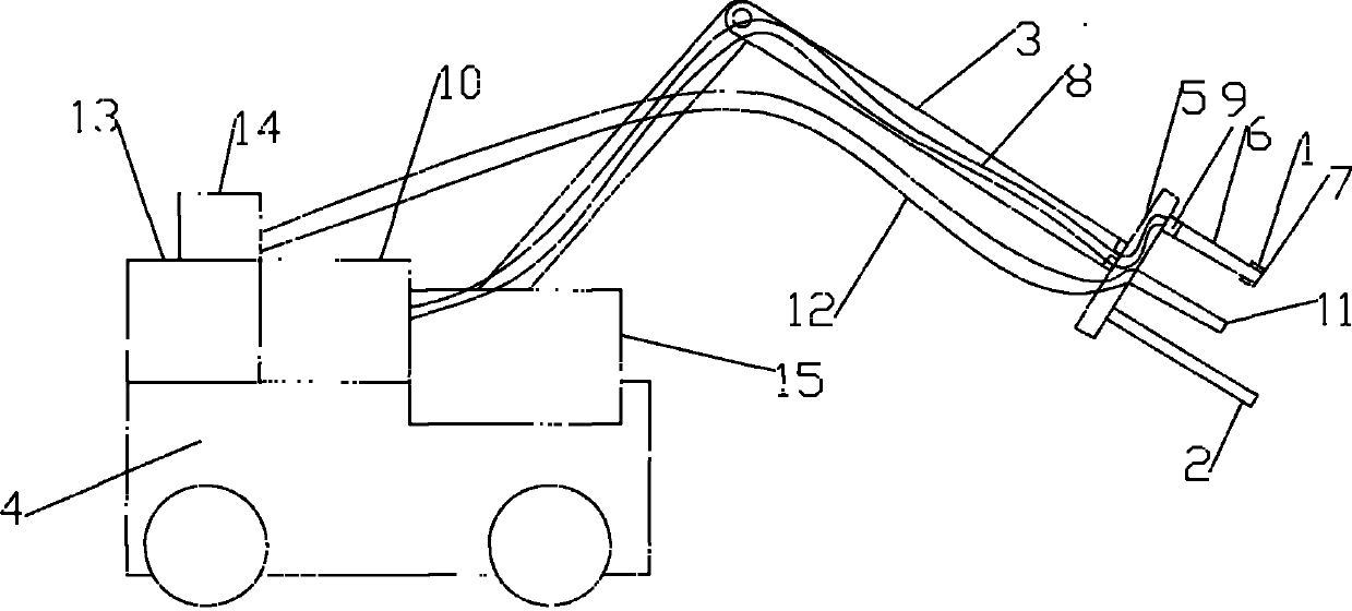
[0007] As shown in the figure, the concrete breaker provided by the present invention includes a high-temperature flame nozzle 1 and an electric drill bit 2, and the high-temperature flame nozzle 1 and the electric drill bit 2 are arranged on the end of a mechanical arm 3, and the mechanical arm 3 is arranged on a transport device 4 for transportation The device 4 is equipped with a control room 15, and the integrated control system of the high-temperature flame nozzle 1 and the electric drill 2 is arranged in the control room 15. The end of the mechanical arm 3 has an electric control turntable 5, and the electric drill 2 and the high-temperature flame nozzle 1 are arranged on The edge position of the electric control turntable 5 is controlled by the integrated control system. The electric control turntable 5 can rotate according to the instructions issued by the integrated control system. During the rotation, the electric drill bit 2 and the high-temperature flame nozzle 1 are...


PUM


Abstract

The invention discloses a concrete breaker, which is characterized in that the concrete breaker comprises a high-temperature flame nozzle and an electric drill bit, the high-temperature flame nozzle and the electric drill bit are arranged at the end part of a mechanical arm, the mechanical arm is arranged on a transportation device, a control room is arranged on the transportation device, and an integrated control system for the high-temperature flame nozzle and the electric drill bit is arranged in the control room. The concrete breaker is practical and convenient.

Description

technical field [0001] The invention relates to a concrete breaker. Background technique [0002] There are still many concrete roads in my country at present, and these roads are often damaged. The traditional repair method is to smash the concrete at the damaged part, then dig out the concrete slag, and finally fill it up with concrete again. However, this repair method takes a long time, especially smashing and digging out concrete slag are generally done manually, which easily affects the smooth flow of the road. Contents of the invention [0003] The technical problem to be solved by the present invention is to provide a concrete breaker that can be used to assist rapid repair of concrete roads. [0004] For this reason the concrete breaker that the present invention provides comprises high-temperature flame nozzle and electric drill bit, and high-temperature flame nozzle and electric drill bit are arranged on the end of mechanical arm, and mechanical arm is arranged...

Claims


Application Information

Patent Timeline
IPC IPC(8): E01C23/12
Inventor 朱奎
Owner 朱奎
Why Eureka
Try Eureka