Optical pointing device and electronic equipment provided with the same, and light-guide and light-guiding method
A technology of optical pointing and light guides, applied in optics, light guides, optical components, etc., can solve problems such as the difficulty of thinning devices, and achieve the effects of reducing manufacturing costs and high detection accuracy
- Summary
- Abstract
- Description
- Claims
- Application Information
AI Technical Summary
Problems solved by technology
Method used
Image

Examples
Embodiment approach 1
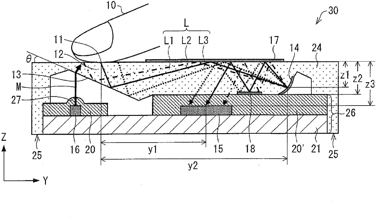
[0035] according to figure 1 Embodiment 1 of the present invention will be described. figure 1It is a schematic cross-sectional configuration diagram of the optical pointing device 30 according to the first embodiment. As shown in the figure, the optical pointing device 30 includes a substrate portion 26 and a cover portion (light guide) 24 . The substrate unit 26 is composed of the circuit board 21, the light source 16, the imaging element 15, and transparent resins 20 and 20'. The transparent resin 20 includes a lens portion 27 . Cover portion 24 includes contact surface (incident portion) 11 , bending element (reflection portion) 12 forming inclined surface (slope) 13 , imaging element (imaging reflection portion) 14 , and reflection surfaces (reflection film) 17 , 18 . The subject 10 in contact with the contact surface 11 of the cover portion 24 is a subject such as a fingertip, and is an object whose motion is to be detected by the optical pointing device 30 . Here, i...
Embodiment approach 2
[0075] according to Figure 4 Embodiment 2 of the present invention will be described. Figure 4 It is a schematic cross-sectional configuration diagram of the optical pointing device 30a of the second embodiment. In the second embodiment, a diffraction element 12' is provided instead of the bending element 12 for totally reflecting the reflected light L in the horizontal direction in the first embodiment. Next, differences between Embodiment 2 and Embodiment 1 due to the provision of the diffraction element 12' will be described. Descriptions of the same configurations in Embodiment 2 as those in Embodiment 1 are omitted.
[0076] like Figure 4 As shown, in the substrate part 26 , the negative side of the Y-axis of the transparent resin 20 is not on the same plane as the side of the circuit board 21 , and the negative side of the Y-axis is located on the positive side of the Y-axis relative to the side of the circuit board 21 . The light M emitted from the light source 1...
Embodiment approach 3
[0090] according to Figure 7 Embodiment 3 of the present invention will be described. Figure 7 It is a schematic cross-sectional structural diagram of the optical pointing device 30b of the third embodiment. In Embodiment 3, the reflective surface 18 included in the cover portion 24 in Embodiment 1 is removed. That is, in Embodiment 3, the cover portion 24 includes the contact surface 11 , the bending element 12 , the imaging element 14 , and the reflection surface 17 . Next, the difference between Embodiment 3 and Embodiment 1 due to the removal of reflective surface 18 will be described. The description of the same structure as that of Embodiment 1 in Embodiment 3 is omitted.
[0091] In Embodiment 3, since there is no reflection surface 18 , the optical path of light L is different from that in Embodiment 1. That is, in Embodiment 3, the reflected light L from the subject 10 is totally reflected toward the reflection surface 17 in the horizontal direction at the incli...
PUM
 Abstract
Description
Claims
Application Information
 - R&D
- Intellectual Property
- Life Sciences
- Materials
- Tech Scout
- Unparalleled Data Quality
- Higher Quality Content
- 60% Fewer Hallucinations
Browse by: Latest US Patents, China's latest patents, Technical Efficacy Thesaurus, Application Domain, Technology Topic, Popular Technical Reports.
© 2025 PatSnap. All rights reserved.Legal|Privacy policy|Modern Slavery Act Transparency Statement|Sitemap|About US| Contact US: help@patsnap.com