
Cutter blade head for fiber roving chopper

A shredder, blade technology, applied in the direction of fiber bundles into fiber sliver/yarn, non-bundle formation, metal processing, etc.

Inactive Publication Date: 2012-09-12
GRACO INC
View PDF5 Cites 8 Cited by
  • Summary
  • Abstract
  • Description
  • Claims
  • Application Information

AI Technical Summary

Problems solved by technology

These techniques are tedious and labor intensive and present a higher risk to the operator because each blade needs to be manipulated when removing the old blade and inserting the new blade into the blade wheel

Method used


Image

  • Cutter blade head for fiber roving chopper
  • Cutter blade head for fiber roving chopper
  • Cutter blade head for fiber roving chopper

Examples


Embodiment Construction

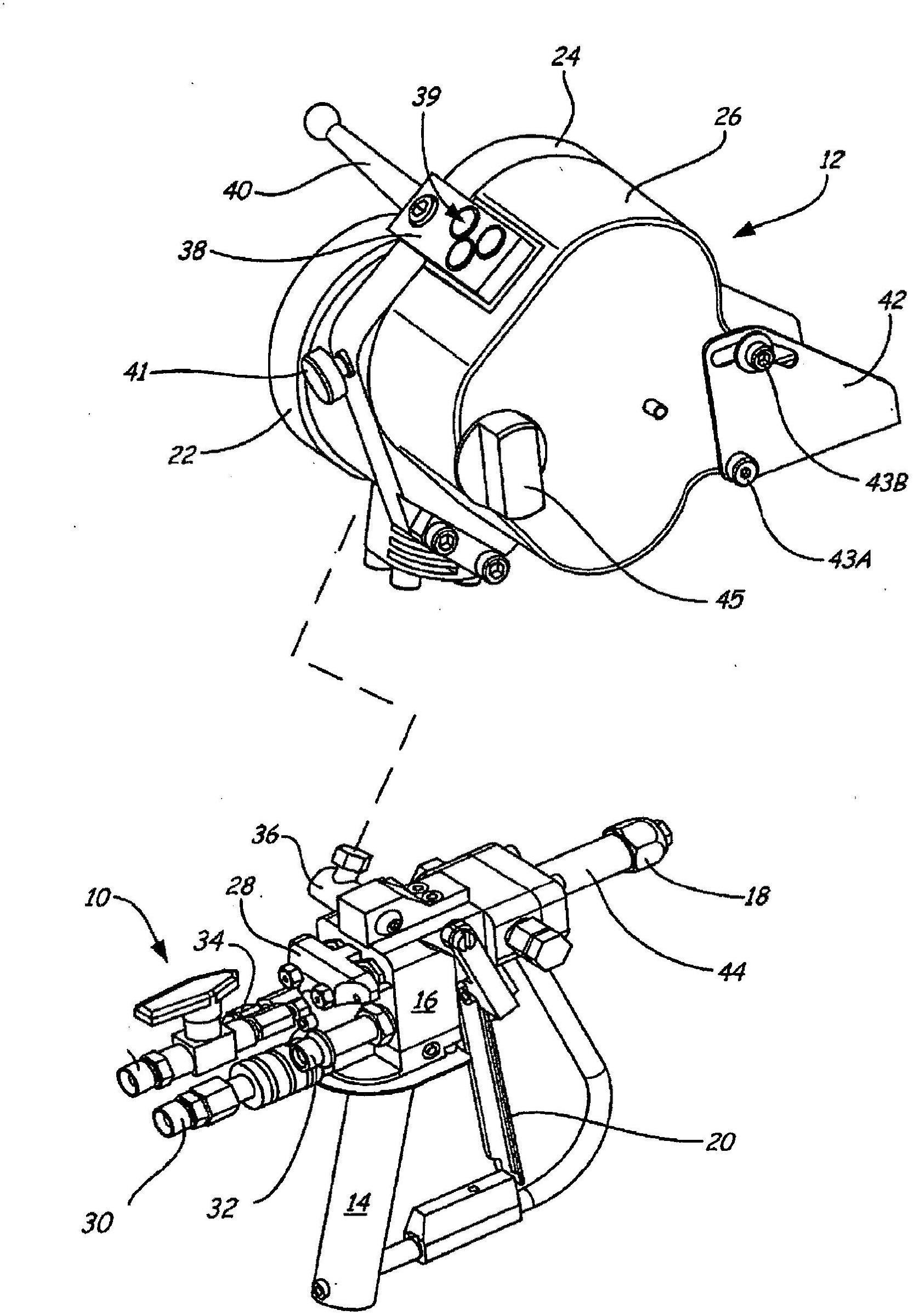
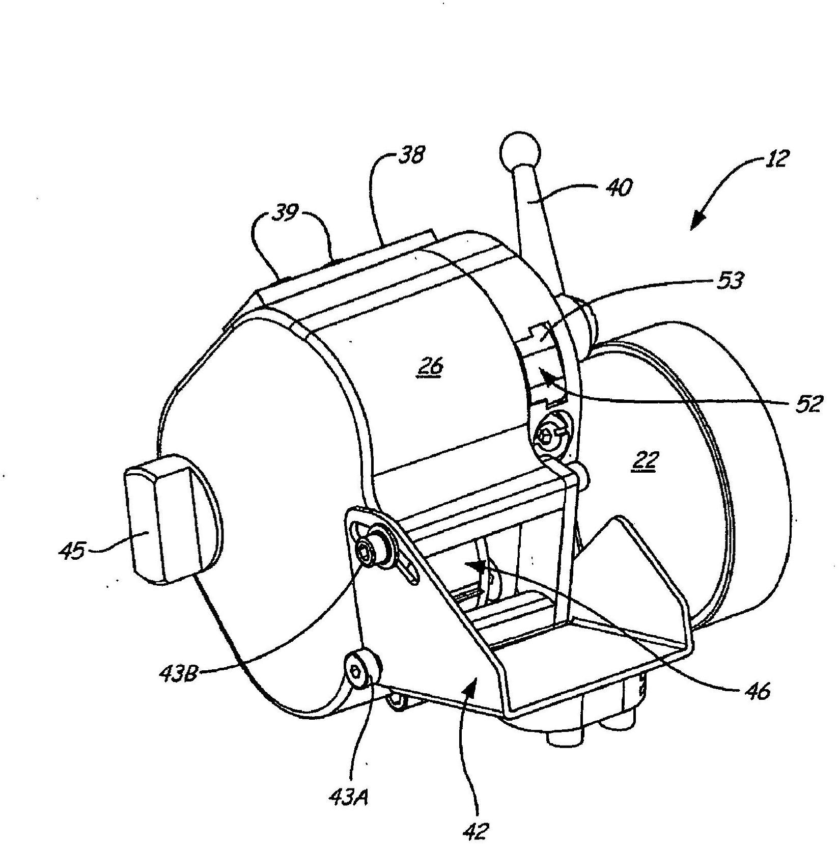
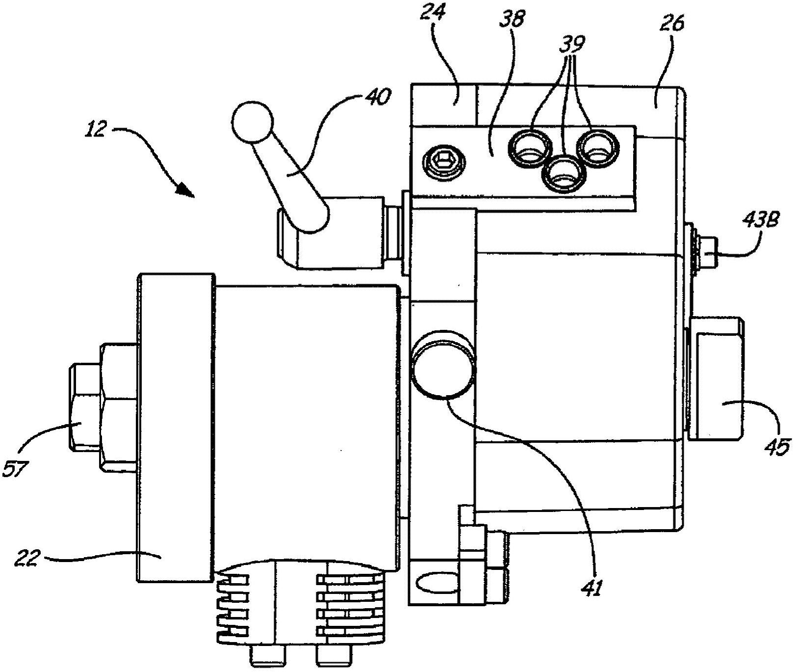
[0023] figure 1 is an exploded view of the assembly of a liquid spray gun and a fiber roving chopper in which the anvil assembly of the present invention is used. exist figure 1 , the fiber roving chopper 12 is shown slightly enlarged relative to the liquid spray gun 10 . The liquid spray gun 10 includes a two-component internal mixing gun having a handle 14 , a valve body 16 , a nozzle 18 and a trigger 20 . The fiber roving chopper 12 includes an air motor 22 , a housing 24 and a cover 26 . The valve body 16 of the spray gun 10 includes a valve assembly 28 , an air inlet 30 , a material inlet 32 ​​, a catalyst inlet 34 and an air outlet 36 . Housing 24 of fiber roving chopper 12 includes fiber inlet 38 , opening 39 , lever 40 , knob 41 , fasteners 43A and 43B, knob 45 and cover 26 , which includes distribution chute 42 .

[0024] In the illustrated embodiment, spray gun 10 comprises a two-component mixing spray gun that receives two liquid components that, when dispensed,...


PUM


Abstract

A blade cartridge for a fiber roving chopper comprises an annular support and a plurality of blade holders. Each of the plurality of blade holders comprises a main body portion, a first end, a second end, and a blade. The first end of the main body portion is connected to the annular support. The second end of the main body portion is opposite the first end such that the main body portion is cantilevered from the annular support. The blade is integrally seated in the main body portion and extends between the first end and the second end. In a further embodiment of the invention, the main body portion of the blade holder includes first and second end notches that extend through the main body portion and the blade.

Description

[0001] Cross References to Related Applications [0002] This application claims the basis of 35 U.S.C. Priority, the content of this application is incorporated by this reference. [0003] This application claims the serial number of the PCT application entitled "CUTTER BLADE HEAD FOR FIBER ROVING CHOPPER" filed on November 23, 2010 by inventors James Rohrer and Jonathan McMichael Priority based on 35 U.S.C. §119 of PCT / 2010 / _____, the content of which application is incorporated by this reference. [0004] This application is related to the following co-pending application filed on the same date as the present invention, by the inventor James Rohrer, entitled "ANVIL FOR FIBER ROVING CHOPPER" and having US Patent Application Serial No._____ / Attorney Docket G372.12-021, the contents of which are incorporated by this reference. technical field [0005] The present invention generally relates to a shredder arrangement which distributes fibrous material into a stream of resin ...

Claims


Application Information

Patent Timeline
Patent Type & Authority Applications(China)
IPC IPC(8): B26D1/36B26D7/00D01G1/04D01G1/10B02C18/18B26D1/62
CPCB05B7/0408B05B7/145B05B7/149B26D1/0006B26D1/40B26D7/2614B26D2001/0033B29B7/7447B29B7/7452B29B7/885B29B7/90D01G1/04D01G1/10B26D1/36B26D1/62B26D7/00
Inventor 詹姆士·H·罗荷尔乔纳森·R·MC迈克尔
Owner GRACO INC
Learn More