
Rail system for drawers

A guide rail system and guide rail technology, applied in the field of guide rail systems, can solve problems such as drawer jamming and guide rail system jamming

Active Publication Date: 2014-04-30
JULIUS BLUM GMBH
View PDF7 Cites 0 Cited by
  • Summary
  • Abstract
  • Description
  • Claims
  • Application Information

AI Technical Summary

Problems solved by technology

In known rail systems, it sometimes arises that the form-locking connection between the rack and the pinion can lead to jamming of the rail system and thus the drawer can accidentally jam in normal use

Method used


Image

  • Rail system for drawers
  • Rail system for drawers
  • Rail system for drawers

Examples


Embodiment Construction

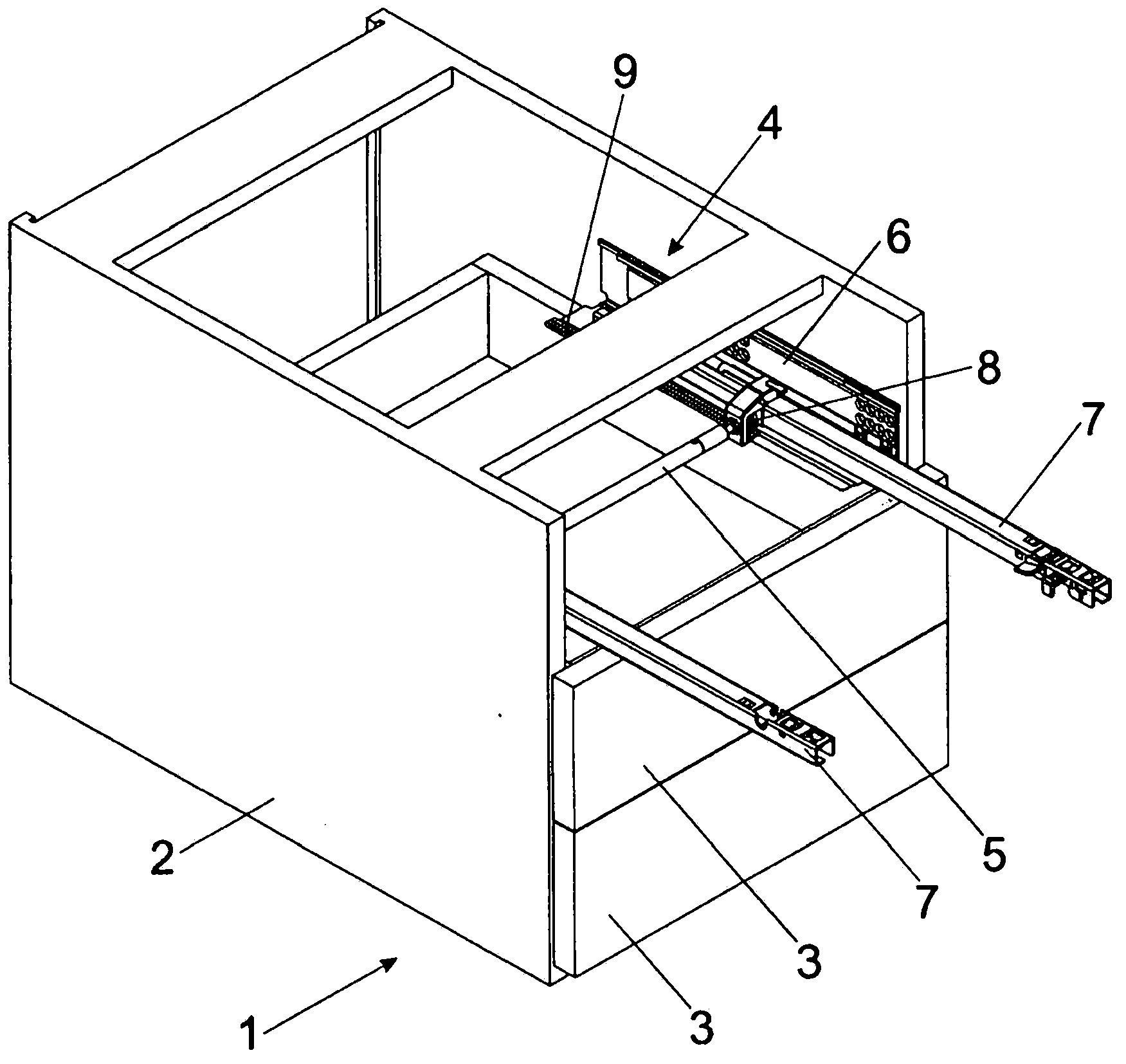
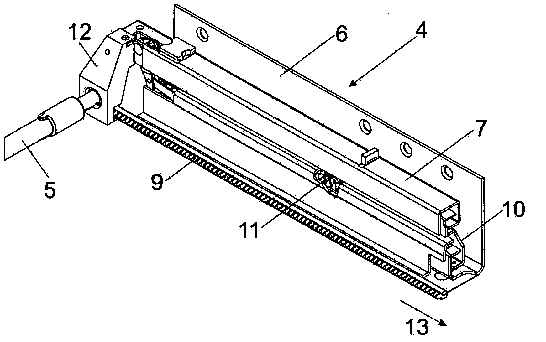
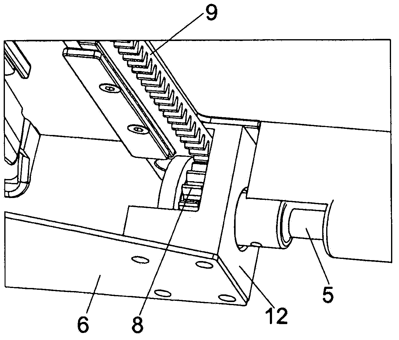
[0023] figure 1 Shown is a perspective view of a piece of furniture 1 with a chest-shaped furniture body 2 , wherein a drawer 3 is mounted displaceably relative to the furniture body 2 via a rail system 4 . On each side of the drawer 3 there is a rail system 4 , wherein the two rail systems 4 are to be fastened to opposite side walls of the furniture cabinet 2 . A synchronizing link 5 in the form of a torsion axis extending transversely to the drawing direction of the drawer 3 can be seen. By means of the synchronizing link 5 , the movements of the two guide rail systems 4 can be synchronized with one another, so that a precise parallel guidance of the drawer 3 relative to the furniture body 2 can be achieved. The two rail systems 4 each have a cabinet rail 6 which is to be fastened to the furniture cabinet 2 and at least one drawer rail 7 which is movable relative to the cabinet rail 6 . The purpose of the synchronizing link 5 is to synchronize the movement of the left and ...


PUM


Abstract

A rail system for drawers includes a body rail to be fastened to a furniture body and at least one drawer rail that can be moved relative to the body rail, and includes at least one gear rack / gear wheel arrangement, characterized in that a limiting device is provided, which limits the immersion depth of the gear wheel relative to the gear rack, the teeth of the gear wheel meshing only partially in the corresponding tooth spaces of the gear rack.

Description

technical field [0001] The invention relates to a rail system for drawers comprising a cabinet rail to be fastened to a furniture cabinet and at least one drawer rail movable relative to said cabinet rail and at least one rack-pinion arrangement . [0002] Furthermore, the invention also relates to an installation unit for two sets of such rail systems as described, which are to be mounted on opposite side walls of the furniture and which are connected to each other by means of synchronizing linkages in order to transmit synchronous movements. connect. Background technique [0003] Such rail systems are usually used to synchronize the movement of two drawer extension guides situated opposite one another on the piece of furniture by means of a rack and pinion arrangement. In this way, a precise parallel guidance of the pull-out furniture parts, in particular drawers, is possible. This parallel guidance relative to the furniture carcass is particularly advantageous when ver...

Claims


Application Information

Patent Timeline
Patent Type & Authority Patents(China)
IPC IPC(8): A47B88/04A47B88/49A47B88/493
CPCA47B88/08A47B2210/0078A47B88/49
Inventor G·施瓦茨曼
Owner JULIUS BLUM GMBH
Learn More