High-voltage large-current transient automatic discharge switch capable of presetting gaps

An automatic discharge, high voltage technology, applied in the direction of circuits, spark gaps, electrical components, etc., can solve the problems of poor controllability and safety, long discharge time and travel, and affect system stability, etc., to achieve easy movement and Flexible placement, short turn-on time, increased discharge reliability and predictable effects

Active Publication Date: 2012-09-12
THE THIRD ENG CORPS RES INST OF THE HEADQUARTERS OF GENERAL STAFF PLA
View PDF7 Cites 5 Cited by
  • Summary
  • Abstract
  • Description
  • Claims
  • Application Information

AI Technical Summary

Problems solved by technology

At present, the existing ball gap spark switch mostly adopts manual adjustment when discharging, the discharge voltage is uncertain, the discharge is sudden, the controllability and safety are not good, and the discharge time and stroke are long.
For the automatic ball gap switch, its structure mostly adopts electronic trigger type, the circuit is complicated, the cost is high, and there are many faults, which affect the stability of the system
Therefore, there is a lack of a transient automatic discharge switch that is small in size, high withstand voltage (hundred kV level), strong current resistance (tens of kA level), good controllability, and high cost performance to meet research needs.

Method used


Image

  • High-voltage large-current transient automatic discharge switch capable of presetting gaps
  • High-voltage large-current transient automatic discharge switch capable of presetting gaps
  • High-voltage large-current transient automatic discharge switch capable of presetting gaps

Examples


Embodiment Construction

[0019] Specific embodiments of the present invention are described with reference to the accompanying drawings.

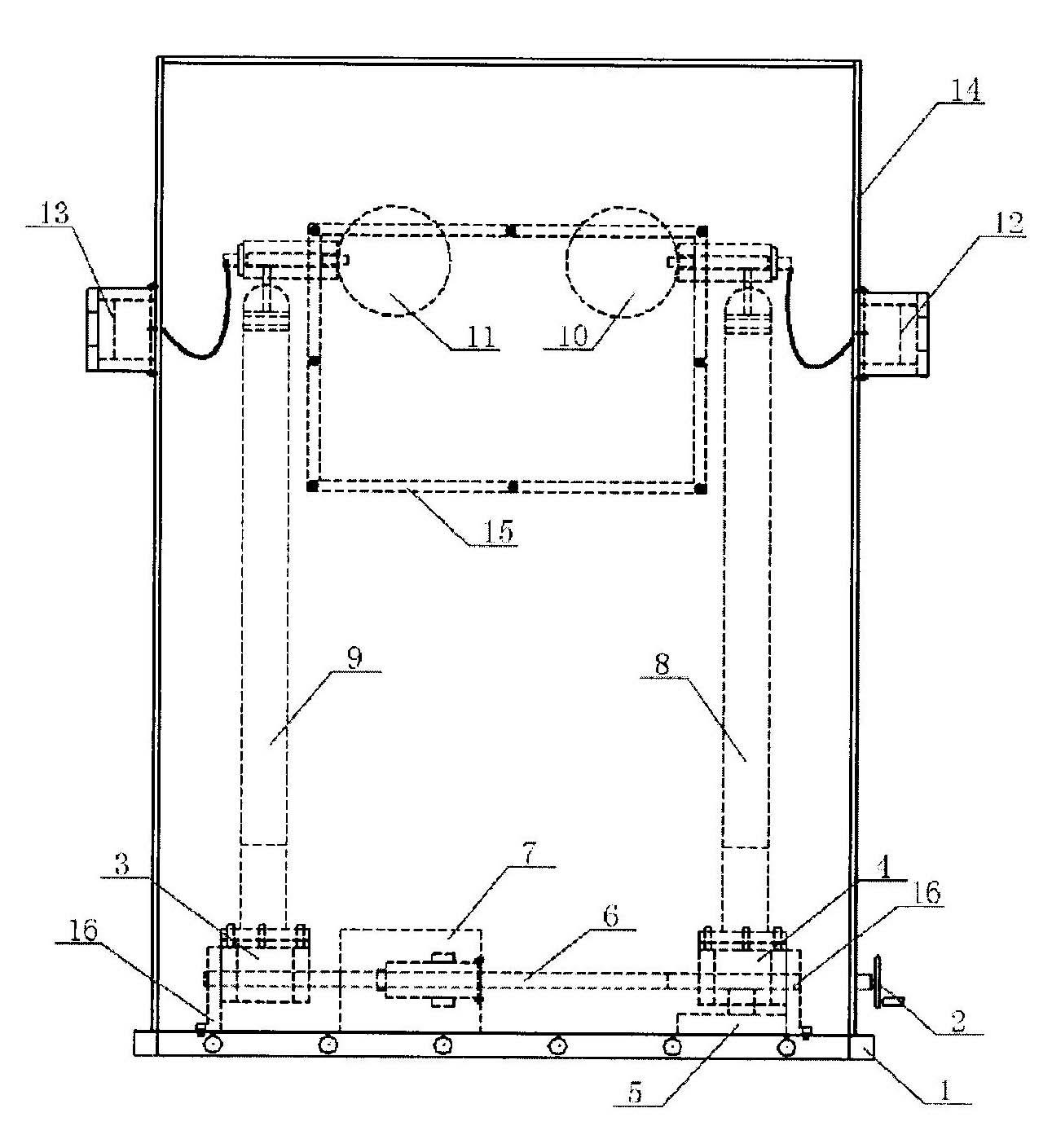
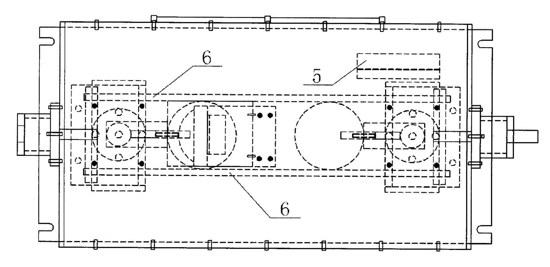
[0020] as attached figure 1 As shown: the discharge switch includes a pair of left and right hollow round copper balls and a switch base, wherein the left ball is an electric ball 11, the right ball is a manual ball 10, and one end of the electric ball 11 is provided with a high-voltage input interface 13, and the manual ball One end of 10 is provided with a high-voltage output interface 12. By controlling the movement of the electric ball 11, the discharge switch forms a variable ball gap switch during charging and discharging. An electric device, a manual device and a guide rail 6 are arranged on the switch base 1, and the two ends of the guide rail 6 pass through the positioning plate 16 Fixed on the switch base 1, the electric device is located at the left end of the guide rail 6. The electric device includes a left slider 4 and an electromagnet 7, the electro...


PUM

PropertyMeasurementUnit
Diameteraaaaaaaaaa
Thicknessaaaaaaaaaa

Abstract

The invention discloses a high-voltage large-current transient automatic discharge switch capable of presetting gaps, which comprises a pair of left and right hollow round copper balls and a switch base (1), wherein the left ball is an electric ball (11), the right ball is a manual ball (10), and the electric ball is controlled to move to enable the discharge switch to become a variable-ball-gap switch in the charging / discharging period; an electric device, a manual device and a guide rail (6) are arranged on the switch base (1); two ends of the guide rail (6) are fixed on the switch base (1)through a positioning plate (16); the electric device is positioned at the left end of the guide rail (6); the electric ball (11) is connected with the electric device through a left isolated uprightrod (9); the manual device is positioned at the right end of the guide rail (6); and the manual ball (10) is connected with the manual device through a right isolated upright rod (8). The switch disclosed by the invention has the advantages of reasonable design, good performance, advanced indexes, compact structure, safety, reliability and high cost performance, and is suitable for applications of pulse power systems.

Description

technical field [0001] The invention relates to the technical field of high-voltage discharge and its control, in particular to a high-voltage and high-current transient automatic discharge switch with a preset gap, which is suitable for high-voltage and high-current transient discharge needs. Background technique [0002] The discharge switch occupies a special position in the pulse power system, because the performance of the switch directly affects the technical parameters of the output pulse, especially the rise time of the output pulse. In addition, switches often work under high voltage and high current, and the working conditions are very harsh. The breakdown phenomenon during the switching process and the physical process of discharge on the switch electrode are very complicated. Therefore, it has the ability to withstand high voltage and high current, and when breakdown The research and development of various types of discharge switching elements that have the chara...

Claims


Application Information

Patent Timeline
IPC IPC(8): H01T1/00H01T1/22H01T14/00
Inventor 李跃波杨杰刘锋潘征何为于浩贾文选黄刘宏闫民华
Owner THE THIRD ENG CORPS RES INST OF THE HEADQUARTERS OF GENERAL STAFF PLA
Why Eureka
Try Eureka