Air entraining structure of engine

A technology of engine and air bleed holes, which is applied in the direction of engine cooling, engine components, machine/engine, etc., can solve the problem of inability to cool down the hot end components, and achieves lower temperature, improved service life and reliability, and good diversion effect. Effect

Active Publication Date: 2012-09-12
CHINA AVIATION POWER MACHINE INST
View PDF6 Cites 4 Cited by
  • Summary
  • Abstract
  • Description
  • Claims
  • Application Information

AI Technical Summary

Problems solved by technology

[0005] The purpose of the present invention is to provide an engine bleed air structure to solve the technical problem that the engine bleed air structure in the prior art cannot effectively cool down the hot end components in a timely manner

Method used


Image

  • Air entraining structure of engine
  • Air entraining structure of engine

Examples


Embodiment Construction

[0020] The embodiments of the present invention will be described in detail below with reference to the accompanying drawings, but the present invention can be implemented in many different ways defined and covered by the claims.

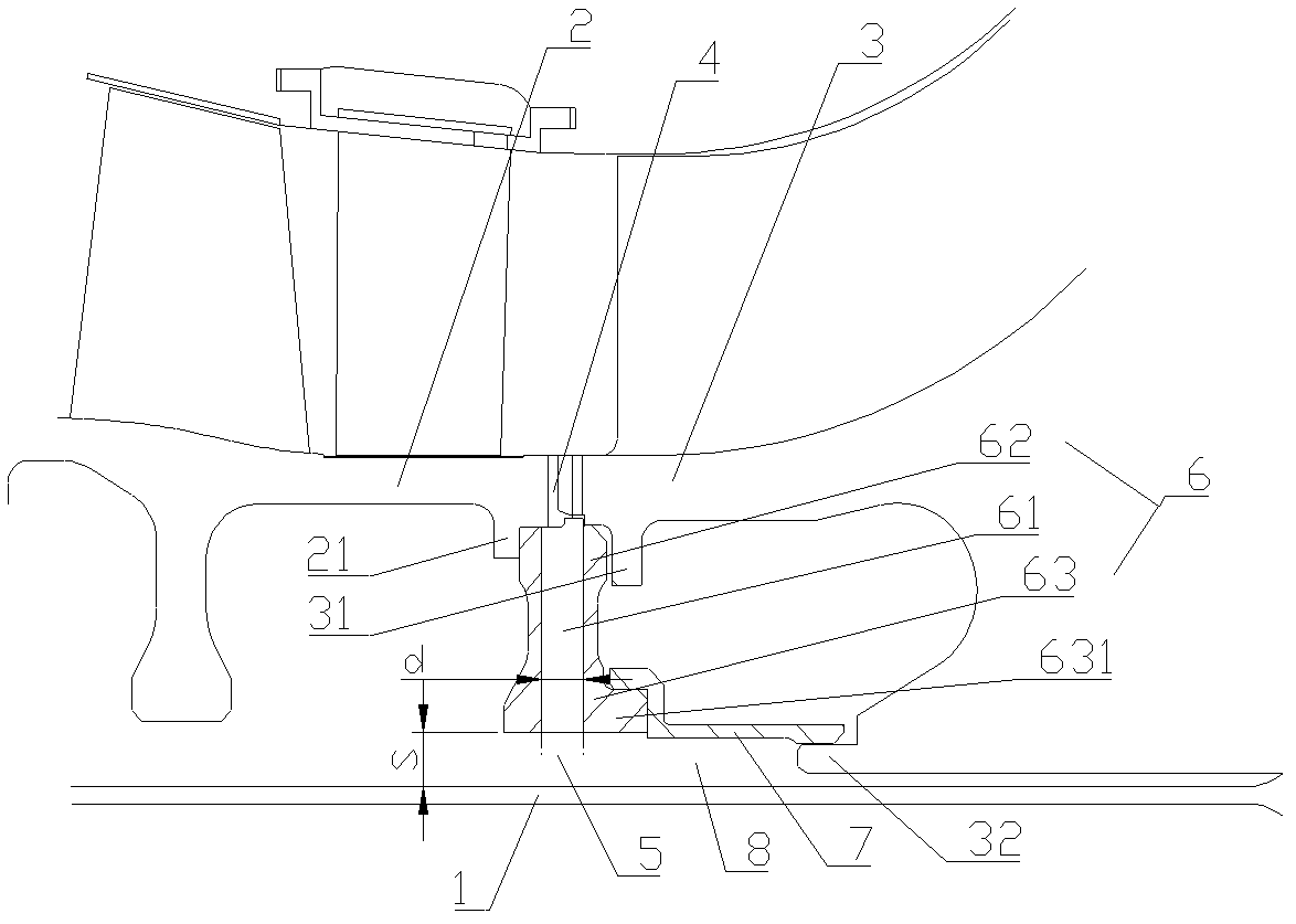
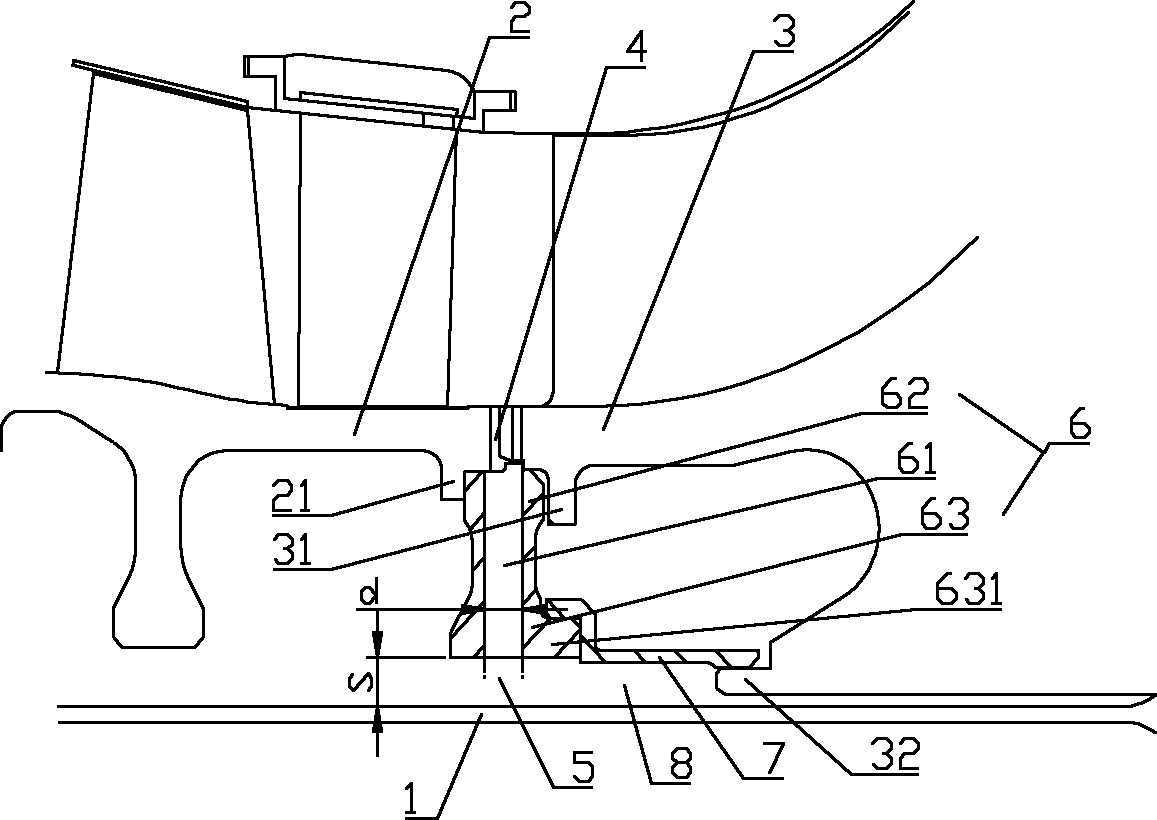
[0021] see figure 1 , The bleed air structure of the engine of the present invention is applied to an aero-engine. The engine includes an inner rotating shaft 1 , a compressor axial flow rotor 2 and a centrifugal impeller 3 . The compressor axial flow rotor 2 and the centrifugal impeller 3 are coaxially and fixedly installed on the inner rotating shaft 1 . A gap 4 is formed between the opposite end surfaces of the compressor axial flow rotor 2 and the centrifugal impeller 3 , and the gap 4 communicates with external cold air. The inner wall surface of one end of the compressor axial flow rotor 2 adjacent to the centrifugal impeller 3 is radially provided with a first collar 21, similarly, the inner wall surface of the centrifugal impeller 3 adjace...


PUM


Abstract

The invention provides an air entraining structure of an engine. The engine comprises an inner rotating shaft, and an axial-flow air compressor rotor and a centrifugal vane wheel which are coaxially and fixedly mounted on the inner rotating shaft, wherein a clearance is formed between two opposite end faces of the axial-flow air compressor rotor and the centrifugal vane wheel and is communicated with cooling air of an external main flow channel. The air entraining structure of the engine comprises an air entraining disc sleeved on the rotor, wherein a first ring-shaped cavity is formed between the inner ring surface of the air entraining disc and the outer peripheral surface of the inner rotating shaft; the air entraining disc is coaxially and fixedly clamped between the axial-flow air compressor rotor and the centrifugal vane wheel and is provided with a plurality of air entraining holes communicated with the first ring-shaped cavity along the radial direction; and each air entraining hole is communicated with the clearance. The air entraining structure of the engine, which is provided by the invention, has the advantages of simple structure, good flow guide effect, convenience in mounting, and the like; and meanwhile, the flux of the cooling air entering into the engine is sufficient and the cooling air can rapidly arrive at a hot end part, so the temperature of the hot end part is effectively reduced, and then the service life of the engine is prolonged and the reliability of the engine is improved.

Description

technical field [0001] The invention relates to the field of aeroengines, in particular to an engine bleed air structure. Background technique [0002] As the power-to-weight ratio of aeroengines continues to increase, the challenges faced by hot-end components are becoming more and more severe. In order to improve the life and reliability of aero-engines, it is critical to reduce the temperature of hot-end components. At present, cold air is introduced between the lower pressure compressor stages to reduce the temperature of the hot end components. However, there are following disadvantages in adopting this kind of bleed air method: [0003] 1. The cold air is subject to great flow resistance during the flow process, and the flow of cold air reaching the hot end components is insufficient; [0004] 2. The cold air is easy to heat up during the flow process, and the high-temperature air-conditioning cannot achieve the effect of cooling the hot end parts. Contents of the...

Claims


Application Information

Patent Timeline
IPC IPC(8): F02C7/12
CPCF04D29/321
Inventor 廖乃冰周志翔贺宜红赵尊盛
Owner CHINA AVIATION POWER MACHINE INST
Why Eureka
Try Eureka