
Iron removal stirring machine

An iron stirring and agitator technology, which is applied in the direction of mixer accessories, chemical instruments and methods, dissolution, etc., can solve the problems of hindering stirring, lack of iron removal function, poor iron removal effect, etc., so as not to affect the effect of stirring and iron removal Good, simple structure effect

Inactive Publication Date: 2012-09-12
HENAN NEWLAND PHARMA
View PDF0 Cites 0 Cited by
  • Summary
  • Abstract
  • Description
  • Claims
  • Application Information

AI Technical Summary

Problems solved by technology

[0002] In the prior art, magnets are placed in the agitator to remove iron from materials, which will hinder stirring; some iron removal technologies use magnets when materials enter or discharge, which has low efficiency and poor iron removal effect. Disadvantages; currently used agitator itself does not have the function of iron removal

Method used


Image

  • Iron removal stirring machine
  • Iron removal stirring machine

Examples


Embodiment Construction

[0011] The present invention will be further described below in conjunction with the accompanying drawings.

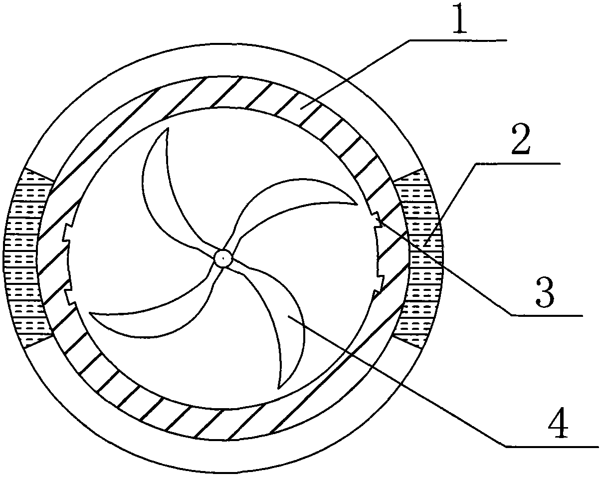
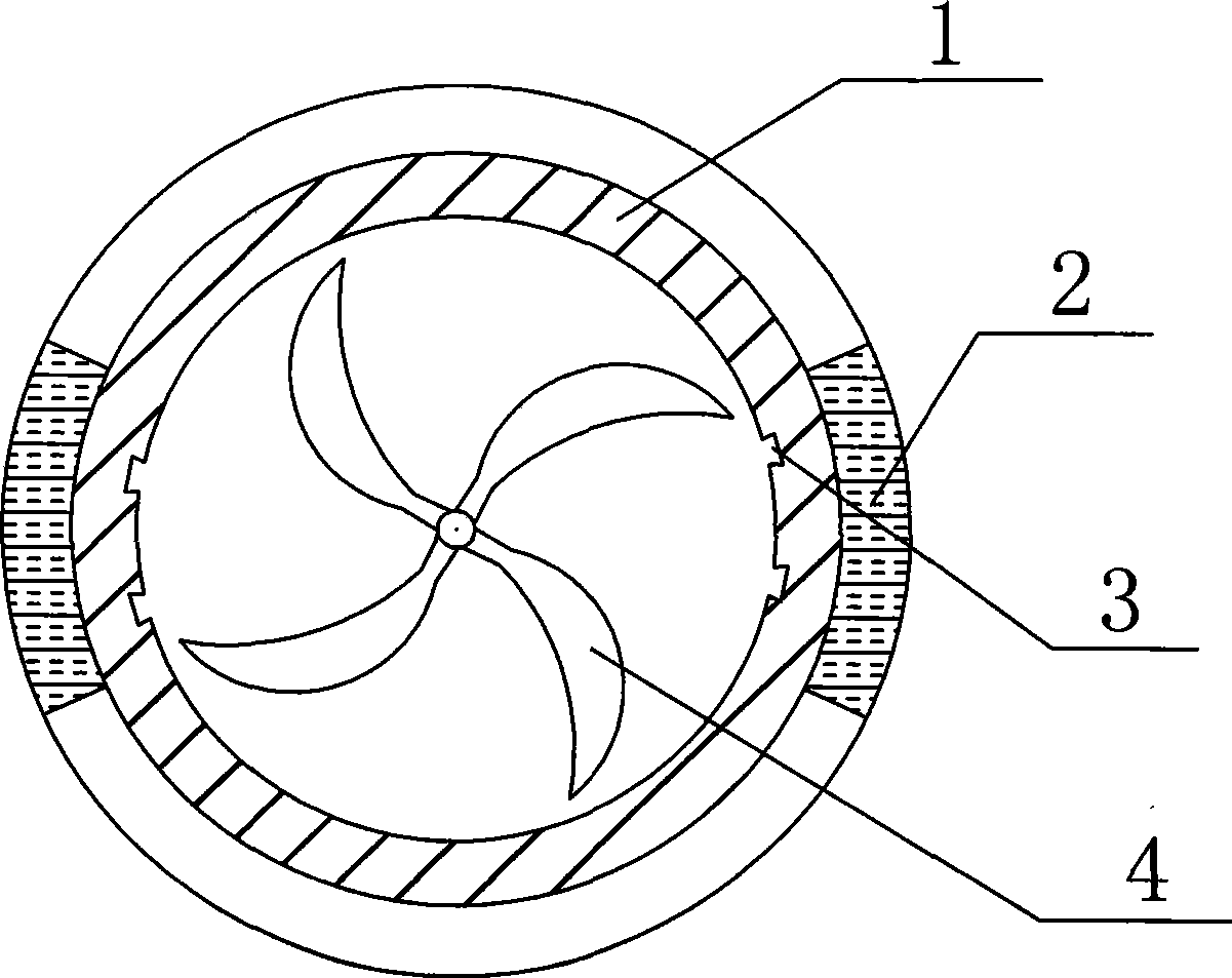
[0012] Such as figure 1 As shown, the iron removal agitator includes an agitator cylinder 1, which is characterized in that: the outside of the agitator cylinder 1 is provided with a magnet 2, and the inside of the agitator cylinder 1 is provided with a groove 3 near the magnetic pole.

[0013] This way, the iron is deposited in the grooves during the stirring process.

[0014] Further speaking, the groove 3 is perpendicular to the running direction of the stirring blade 4 .

[0015] In this way, the iron removal effect will be better.

[0016] Further speaking, the groove 3 is a square groove or a dovetail groove. In this way, the iron deposited in the groove is not easy to run out.

[0017] Further speaking, the depth of the groove 3 is 1-2 cm.

[0018] This will deposit less material and also achieve the purpose of depositing iron.

[0019] If the material con...


PUM


Abstract

The invention relates to the technical fields of chemical industry, pharmacy and the like, in particular to a stirring machine, and the stirring machine is an iron removal stirring machine. The stirring machine comprises a cylinder body, a magnet is arranged outside the cylinder body, a groove is arranged inside the cylinder body close to a magnetic pole, the groove is perpendicular to a revolving direction of stirring blades, the groove is a square groove or a dovetail groove, and a depth of the groove is 1-2 centimeters. The iron removal stirring machine with the structure has the advantages that the iron removal effect is good, the structure is simple, and the stirring is not affected.

Description

technical field [0001] The invention relates to technical fields such as chemical industry and pharmacy, in particular to a stirrer. Background technique [0002] In the prior art, magnets are placed in the agitator to remove iron from materials, which will hinder stirring; some iron removal technologies use magnets when materials enter or discharge, which has low efficiency and poor iron removal effect. Disadvantages; the currently used agitator itself does not have the function of iron removal. Contents of the invention [0003] The object of the present invention is to address the above-mentioned disadvantages and provide an iron removal agitator with good iron removal effect, simple structure and no influence on stirring. [0004] The technical solution of the present invention is realized in the following way: the iron removal agitator includes an agitator cylinder, which is characterized in that: the outside of the agitator cylinder is provided with a magnet, and th...

Claims


Application Information

Patent Timeline
Patent Type & Authority Applications(China)
IPC IPC(8): B01F15/00
Inventor 谢建中张芦苇刘万民
Owner HENAN NEWLAND PHARMA
Learn More