Storage battery system and storage battery module

A battery module and battery system technology, which is applied in the field of battery systems, can solve the problems of reduced charge and discharge capacity, performance decline, uneven charge and discharge capacitance, etc., and achieve the effect of safe replacement

Inactive Publication Date: 2012-08-29
HITACHI LTD
View PDF5 Cites 0 Cited by
  • Summary
  • Abstract
  • Description
  • Claims
  • Application Information

AI Technical Summary

Problems solved by technology

[0003] However, when variations occur in the voltage and charge / discharge capacity of each battery module due to elapse of time, etc., the charge / discharge capacity borne by these battery modules becomes non-uniform, degrading the performance of the entire system.
The reason is that the battery modules are connected in series, so if the difference in charge and discharge capacitance among the battery modules becomes large, the discharge capacity will be limited by the module with less capacitance during discharge, and the module with large remaining power will be fully charged first when charging. As a result, charging can no longer be continued, and the overall charging and discharging capacity of the system is reduced.

Method used


Image

  • Storage battery system and storage battery module
  • Storage battery system and storage battery module
  • Storage battery system and storage battery module

Examples


Embodiment 1

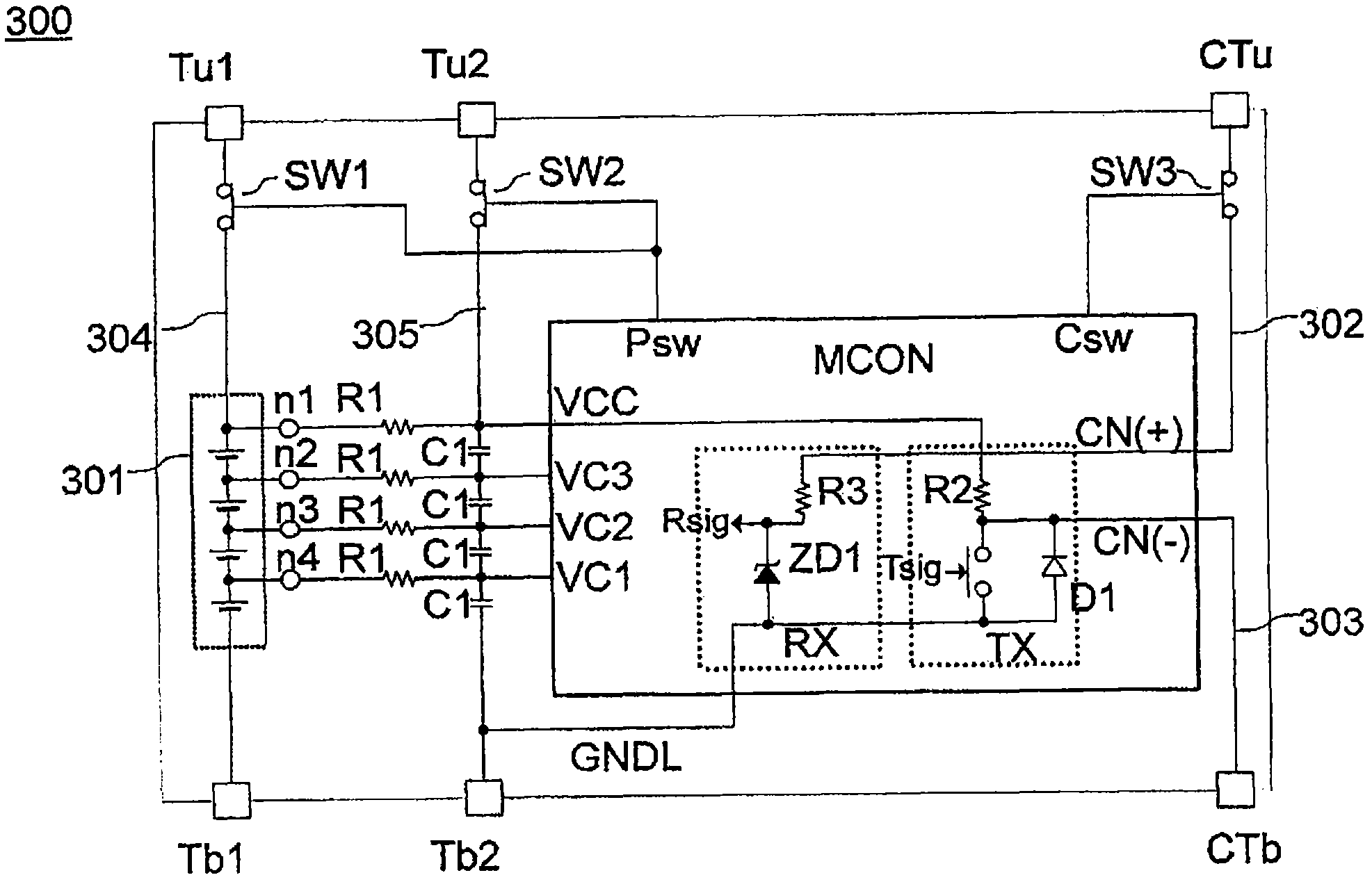
[0037] The first embodiment will be described. In the first embodiment, a battery system is constituted by a battery module incorporating a switch. image 3 is a block diagram showing the main configuration of the battery module 300 . as figure 1The battery module of the battery system is used. The storage battery module has a series-connected cell string 301 , a module controller MCON, and a switch SW for disconnecting the external terminals of the module from the internal elements. The cell array 301 is, for example, a secondary battery such as a lithium ion battery cell. The module controller MCON obtains the information of the voltage, current, temperature, etc. of the single battery, and communicates with the control device SCON through the communication line 302 and the communication line 303 connected in series with other modules. In this example, a transmission circuit TX and a reception circuit RX for unidirectional communication with the control device SCON are s...

Embodiment 2

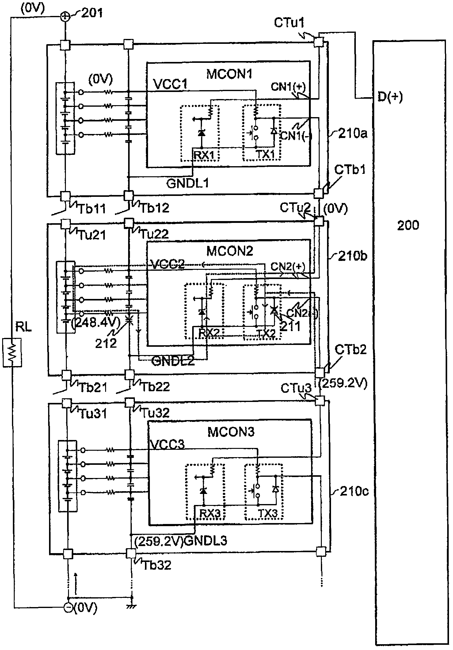
[0052] The second embodiment will be described. In the second embodiment, insulation breakdown of the internal elements of the module is prevented by making the structure of the external terminals of the storage battery module different in the power supply terminal and the communication terminal. In the second embodiment, the internal structure of the battery module is equivalent to figure 2 The structure of 210.

[0053] Figure 9 , Figure 10 The external appearance and cross-sectional view of the battery module 900 according to the second embodiment are respectively shown. A communication connector 901 and power supply connectors (positive and negative poles) 903 and 904 are provided on the back portion of the battery module case 905 . If it is a module supporting bidirectional communication, four communication connectors 901 are provided. Such as Figure 10 As shown, the front end of the communication connector 901 is shorter than the front ends of the power supply ...


PUM


Abstract

A storage battery system in which multiple storage battery modules are connected in series and such that deteriorated storage battery modules may be made replaceable without causing dielectric breakdown. The storage battery system is one that has multiple storage battery modules (510-530) connected in series and has a mechanism (521,522) of, when the storage battery module is detached, disconnecting power source line connected to the storage battery modules (520) after disconnecting communication line connected to the storage battery modules (520).

Description

technical field [0001] The invention relates to a battery module and a battery system composed of a plurality of battery modules. Background technique [0002] In the present invention, a plurality of single cells (for example, Li-ion battery cells) connected in series are used as a battery module. A storage battery system has been developed for increasing the voltage and obtaining high output power by using the battery module as a unit and connecting a plurality of them in series. [0003] However, when the voltage and charge / discharge capacity of each battery module vary over time or the like, the charge / discharge capacity borne by these battery modules becomes non-uniform, degrading the performance of the entire system. The reason is that the battery modules are connected in series, so if the difference in charge and discharge capacitance among the battery modules becomes larger, the discharge capacity will be limited by the module with less capacitance during discharge,...

Claims


Application Information

Patent Timeline
Patent Type & Authority Applications(China)
IPC IPC(8): H01M10/42H02J7/02
CPCH01M6/42H01M10/4207H01M10/482G01R31/396Y02E60/10
Inventor 竹内隆寺田崇秀长田健一
Owner HITACHI LTD
Why Eureka
Try Eureka