
Over temperature protection circuit used for power device

A technology for over-temperature protection circuits and power devices, applied in emergency protection circuit devices, emergency protection devices for automatic disconnection, circuit devices, etc., can solve the problems of power devices that cannot be turned off reliably, and prevent unstable turn-on and turn-off The effects of intermittent oscillation, wide power application range, and low power consumption

Inactive Publication Date: 2012-08-22
UNIV OF ELECTRONICS SCI & TECH OF CHINA +1
View PDF5 Cites 15 Cited by
  • Summary
  • Abstract
  • Description
  • Claims
  • Application Information

AI Technical Summary

Problems solved by technology

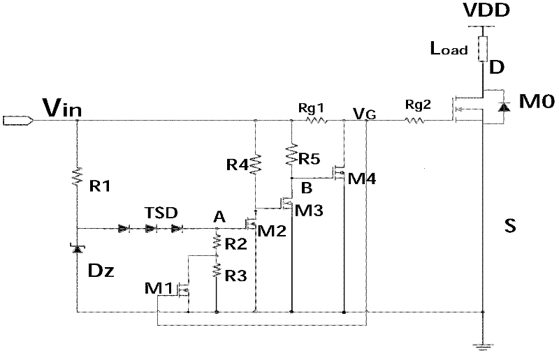
[0005] In order to solve the defect that the power device cannot be reliably shut down after the over-temperature protection in the traditional over-temperature protection scheme, the present invention proposes an over-temperature protection circuit for the power device

Method used


Image

  • Over temperature protection circuit used for power device
  • Over temperature protection circuit used for power device
  • Over temperature protection circuit used for power device

Examples


Embodiment Construction

[0023] In order to make the purpose and technical solution of the present invention clearer, the present invention will be further described in detail below in conjunction with specific embodiments and with reference to the accompanying drawings.

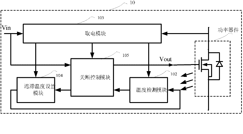
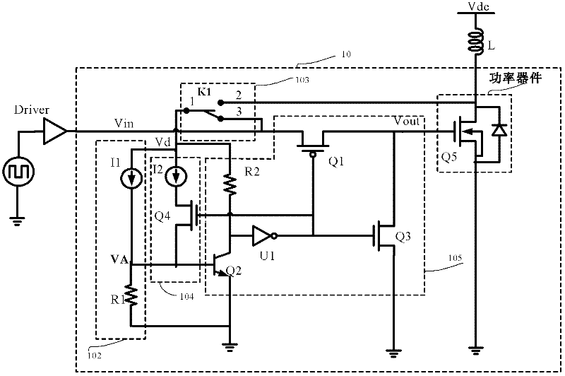
[0024] Such as figure 2 As shown, an over-temperature protection circuit 10 for power devices includes: a temperature detection module 102, a shutdown control module 105, a hysteresis temperature setting module 104 and a power-taking module 103, wherein,

[0025] The power-taking module 103 includes a first input terminal and a second input terminal, the first input terminal is connected to the external drive signal Vin, and the second input terminal is connected to the high potential conduction pole of the power device , the output terminal of the temperature detection module 102 is connected to the first input terminal of the shutdown control module 105, the temperature detection module 102 is used to detect the temperature of th...


PUM


Abstract

The invention discloses an over temperature protection circuit used for a power device, and the over temperature protection circuit specifically comprises a temperature detection module, a cutoff control module, a delay temperature setting module and an electrifying module. The over temperature protection circuit requires no separate reference voltage source and can be electrified both from input signals and from a protected power device. The thermal induction source for temperature detection is a current source with the current value being direct proportional to the temperature. When the temperature reaches the over temperature point, the current path between a pre-driver and the power device is cut off by the cutoff control module, the power device can be reliably cut off and the overall power consumption under over temperature is the lowest. According to the invention, the delay temperature can be set by adjusting the proportion of the two current sources, and the protection can be relieved after the temperature is lower for one delay temperature than the over temperature point, so oscillation near the over temperature point can be effectively avoided and the power device can not be turned on by mistake.

Description

technical field [0001] The invention relates to an over-temperature protection circuit suitable for power devices, especially suitable for the field of power integration. Background technique [0002] Power devices are currently one of the most widely used and most efficient power electronic devices. However, power devices may generate a lot of heat during operation. If the heat dissipation is not effective and the over-temperature protection circuit is unreliable, it is easy to cause thermal breakdown of the device and cause permanent damage to the device. [0003] The over-temperature protection scheme that is often used at present usually uses the BE junction of bipolar transistors, such as "an over-temperature protection circuit" disclosed in application number 2009102367211, and thermal diodes, such as the "MOS type over-temperature protection circuit" disclosed in application number 200720036138.2. Or a thermistor is used as a thermal sensing source. The output signal...

Claims


Application Information

Patent Timeline
Patent Type & Authority Applications(China)
IPC IPC(8): H02H7/20H02H5/04
Inventor 李泽宏张仁辉黄斌蒋汇任敏张金平张波
Owner UNIV OF ELECTRONICS SCI & TECH OF CHINA
Learn More