Combination type heat storage water tank of external disk heat storage casting box and condensation heat exchanger
A technology of condensing heat exchanger and hot water storage tank, which is used in fluid heaters, lighting and heating equipment, etc., to achieve the effect of improving response speed, increasing heat exchange efficiency and ensuring safety
- Summary
- Abstract
- Description
- Claims
- Application Information
AI Technical Summary
Problems solved by technology
Method used
Image
Examples
Embodiment 1
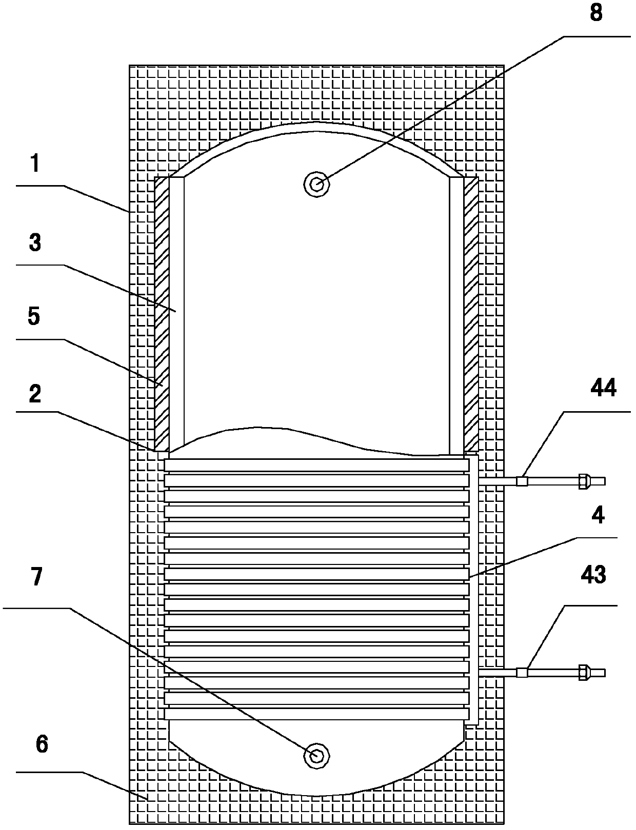
[0037] like figure 1 As shown, a hot water storage tank of an outer disk type condensing heat exchanger includes an outer shell 1, a heat storage mold box 2, a heat storage material 5, a water tank liner 3, a condensing heat exchanger 4 and a thermal insulation material 6. The heat storage material 5 is filled in the heat storage mold box 2, and the phase change temperature point of the heat storage material 5 is between the inlet and outlet water temperatures; the heat insulation material 6 is foamed between the shell 1 and the water tank liner 3, and the water tank liner 3 There are water inlet and outlet ports 7 and 8; the heat storage mold box 2 is outsourced on the outer wall of the water tank liner 3, and the heat storage mold box 2 and the water tank liner 3 are integrally formed; the condensing heat exchanger 4 is outsourced in the water tank The outer wall of the bile 3; the heat storage mold box 2 is arranged on the upper part of the water tank, and the condensing he...
Embodiment 2
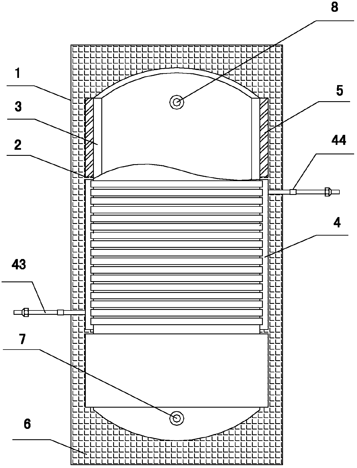
[0041] like figure 2 Shown, the difference between this embodiment and embodiment 1 is:
[0042] The heat storage mold box 2 is arranged at the upper and lower parts of the water tank, and the condensation heat exchanger 4 is arranged at the middle part of the water tank.
[0043] The condensing heat exchanger 4 is formed by connecting two microchannel condensers in parallel, the inlet headers 42 of the two microchannel condensers are communicated through the refrigerant flow pipe 45, and the outlet headers 46 of the two microchannel condensers are connected through The refrigerant circulation pipes 45 are connected. One of the refrigerant circulation pipes is located at the lower part of the outlet header 46 and communicates with the refrigerant outlet pipe 43 . The other refrigerant circulation pipe is located at the upper part of the inlet header 42 and communicates with the refrigerant inlet pipe 44 .
Embodiment 3
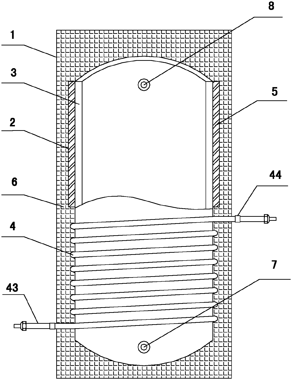
[0045] like image 3 Shown, the difference between this embodiment and embodiment 1 is:
[0046] The condensing heat exchanger 4 is a coil heat exchanger with a D-shaped cross section.
PUM
 Abstract
Description
Claims
Application Information
 - R&D
- Intellectual Property
- Life Sciences
- Materials
- Tech Scout
- Unparalleled Data Quality
- Higher Quality Content
- 60% Fewer Hallucinations
Browse by: Latest US Patents, China's latest patents, Technical Efficacy Thesaurus, Application Domain, Technology Topic, Popular Technical Reports.
© 2025 PatSnap. All rights reserved.Legal|Privacy policy|Modern Slavery Act Transparency Statement|Sitemap|About US| Contact US: help@patsnap.com


