Hydrocone type multi-stage hydroelectric generation method
A technology of siphon type and siphon pipes, which is applied in hydropower, engine components, machines/engines, etc., can solve the problems of large geographical restrictions and high project cost, and achieve the effect of low project cost, small geographical restrictions and stable flow rate
- Summary
- Abstract
- Description
- Claims
- Application Information
AI Technical Summary
Problems solved by technology
Method used
Image
Examples
Embodiment 1
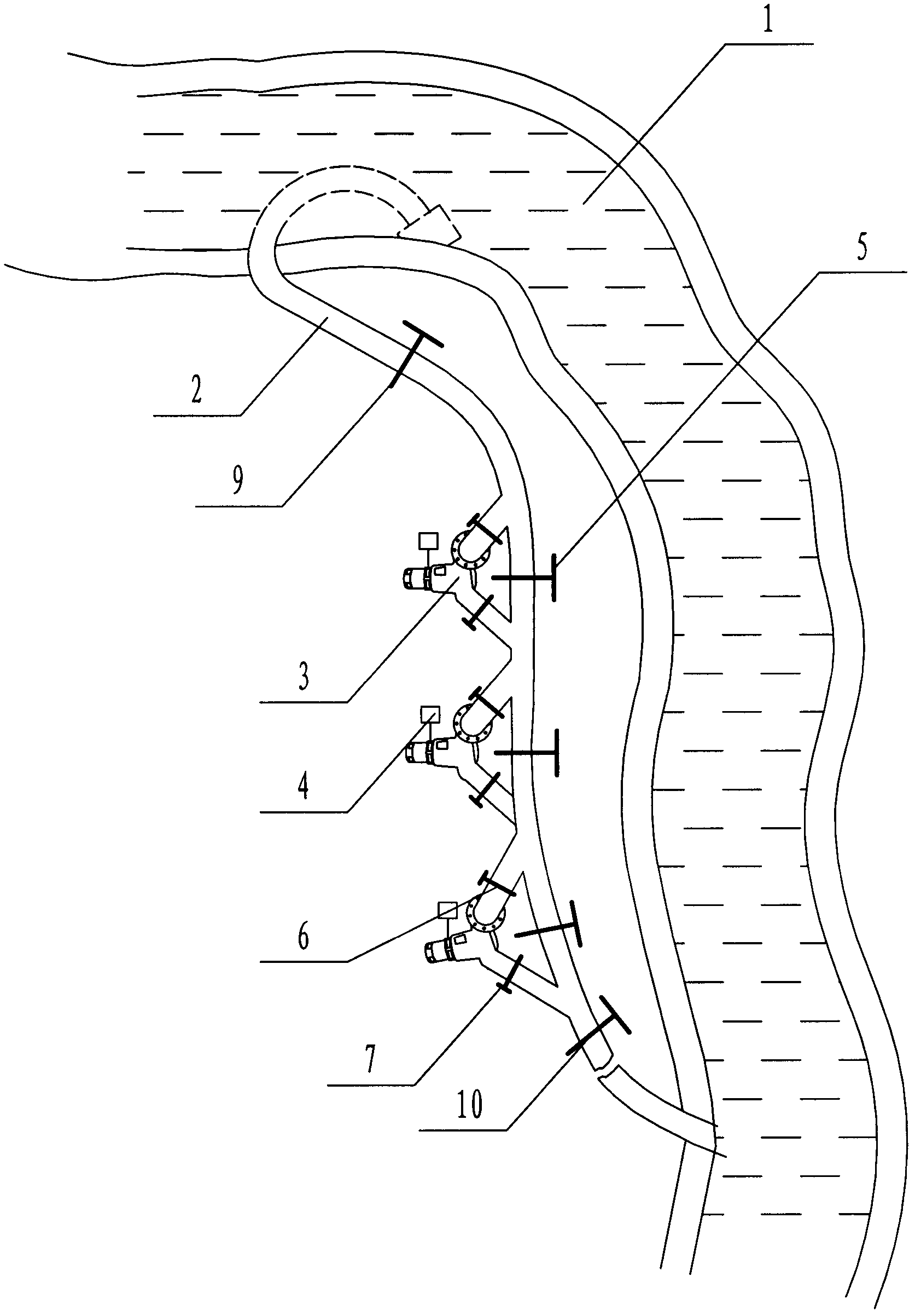
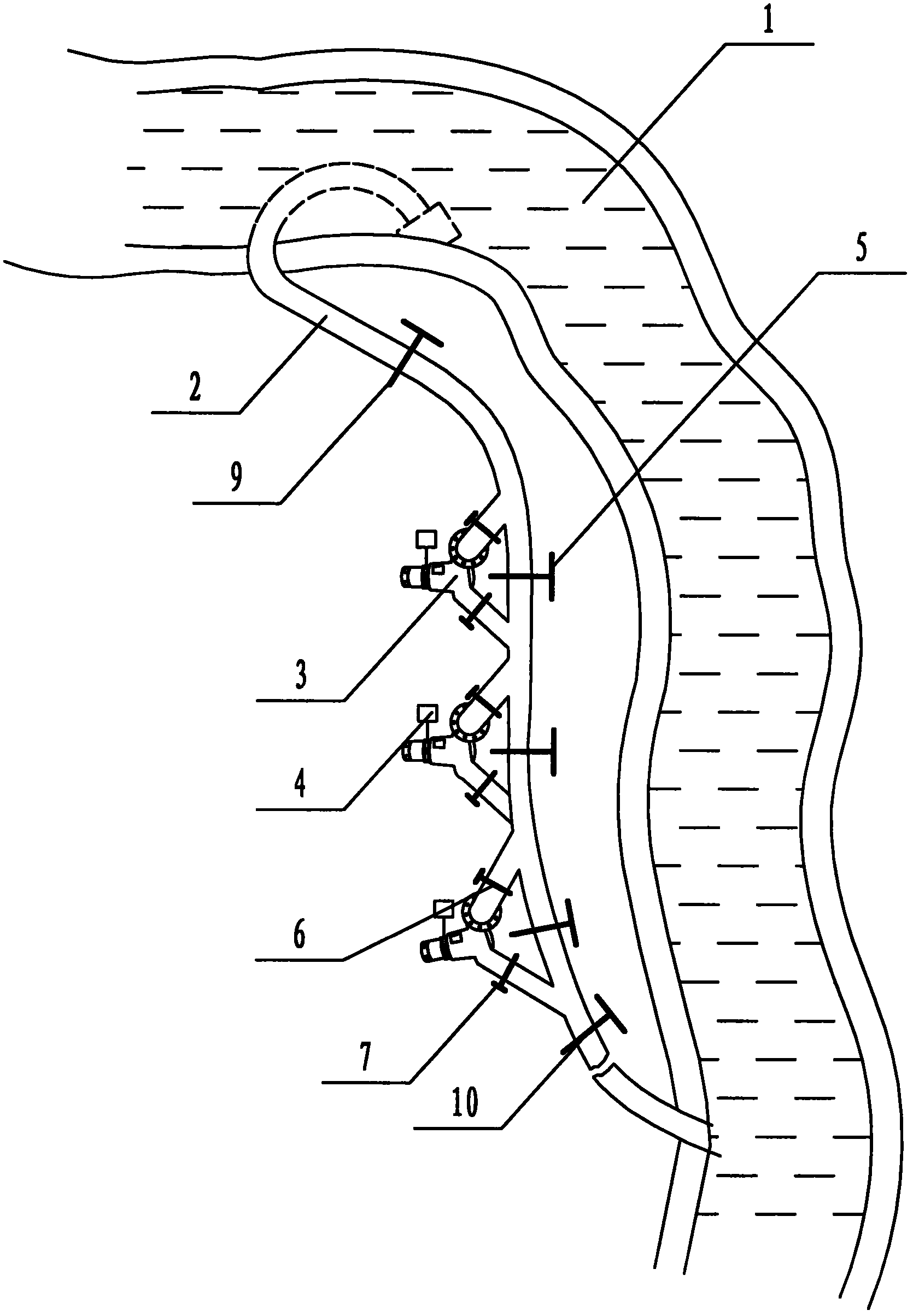
[0024] As attached figure 1 As shown, the siphon-type multi-stage hydroelectric power generation method of the present invention first selects a section of the river basin 1 with a water flow drop, and installs the water inlet end of the siphon pipe 2 in the upper water area of the water flow drop. The water flow drop section is laid, and the water outlet end of the siphon pipe 2 is introduced into the lower water area of the water flow drop section or other discharge places; a set or a set of pipe sections where the water flow pressure difference of the siphon pipe 2 reaches the power generation speed requirements of the hydro-generator set In the above-mentioned hydro-electric generator sets 3, each hydro-electric generator set 3 is connected to the parallel control system 4. The parallel control system 4 includes a flow control unit, a flow rate control unit, and a pressure difference control unit. The control units work in coordination to make the hydraulic turbine gener...
Embodiment 2
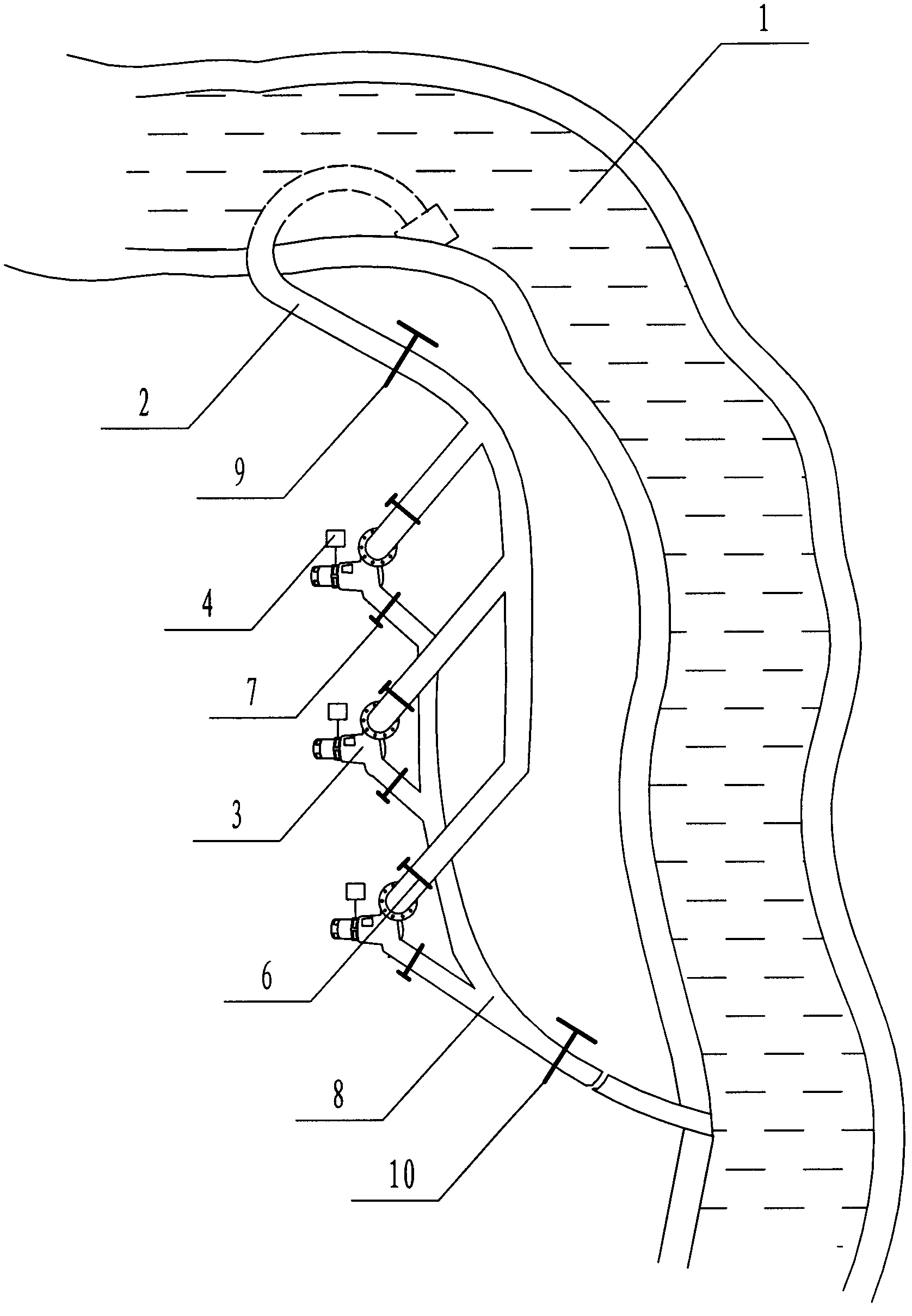
[0027] As attached figure 2 As shown, the siphon-type multi-stage hydroelectric power generation method of the present invention first selects a section of the river basin 1 with a water flow drop, and installs the water inlet end of the siphon pipe 2 along the upper water area of the water flow drop section. Following the laying of the water flow drop section, the water outlet end of the siphon pipe 2 is introduced into the lower water area of the water flow drop section or other discharge places; a set of pipe sections or pipe sections where the water flow pressure difference of the siphon pipe 2 reaches the power generation speed requirements of the hydro-generator unit 3 There are more than one group of hydroelectric generator sets 3, and each hydroelectric generator set 3 is connected to the parallel control system 4. The parallel control system 4 includes a flow control unit, a flow rate control unit, and a pressure difference control unit. The control units work in ...
PUM
 Abstract
Description
Claims
Application Information
 - R&D
- Intellectual Property
- Life Sciences
- Materials
- Tech Scout
- Unparalleled Data Quality
- Higher Quality Content
- 60% Fewer Hallucinations
Browse by: Latest US Patents, China's latest patents, Technical Efficacy Thesaurus, Application Domain, Technology Topic, Popular Technical Reports.
© 2025 PatSnap. All rights reserved.Legal|Privacy policy|Modern Slavery Act Transparency Statement|Sitemap|About US| Contact US: help@patsnap.com


