
Selective harmonic wave extracting method

A harmonic extraction and selective technology, applied in the field of signal processing, can solve the problems of redundant algorithm, occupying system resources, unfavorable harmonic detection unit and harmonic controller performance design and inspection, etc. less effect

Active Publication Date: 2012-08-08
ZHEJIANG UNIV
View PDF5 Cites 12 Cited by
  • Summary
  • Abstract
  • Description
  • Claims
  • Application Information

AI Technical Summary

Problems solved by technology

Lascu.C et al. proposed a frequency-selective characteristic in an article titled High Performance Current Controller for Selective Harmonic Compensation in Active Power Filters (Power Electronics, IEEE Transactions on, 2007.22(5): p.1826-1835). The resonant controller, which embeds the selective harmonic detection function into the controller of the current loop, realizes selective harmonic control. This method combines harmonic detection and harmonic control into one, although the complexity It is simple, but changes the structure of the controller, which is not conducive to the separate design and investigation of the performance of the harmonic detection unit and the harmonic controller, and reduces the flexibility of the system. At the same time, when the grid frequency fluctuates, the extraction of harmonics will exist. large deviation
Xue Hui and others introduced a FFT algorithm for selective harmonic detection in an article titled High-precision Harmonic Detection Algorithm Based on FFT (Proceedings of the Chinese Society for Electrical Engineering, 2002 (12): pp. 107-111). This method can adopt the same traditional harmonic control strategy, but the algorithm is relatively tedious and inefficient, which makes the program occupy a large amount of system resources, especially when the number of harmonics selectively extracted is large, the resources occupied by the algorithm are usually traditional hardware systems. hard to accept

Method used


Image

  • Selective harmonic wave extracting method
  • Selective harmonic wave extracting method
  • Selective harmonic wave extracting method

Examples


Embodiment Construction

[0044] In order to describe the present invention more specifically, the method of the present invention will be described in detail below in conjunction with the accompanying drawings and specific embodiments.

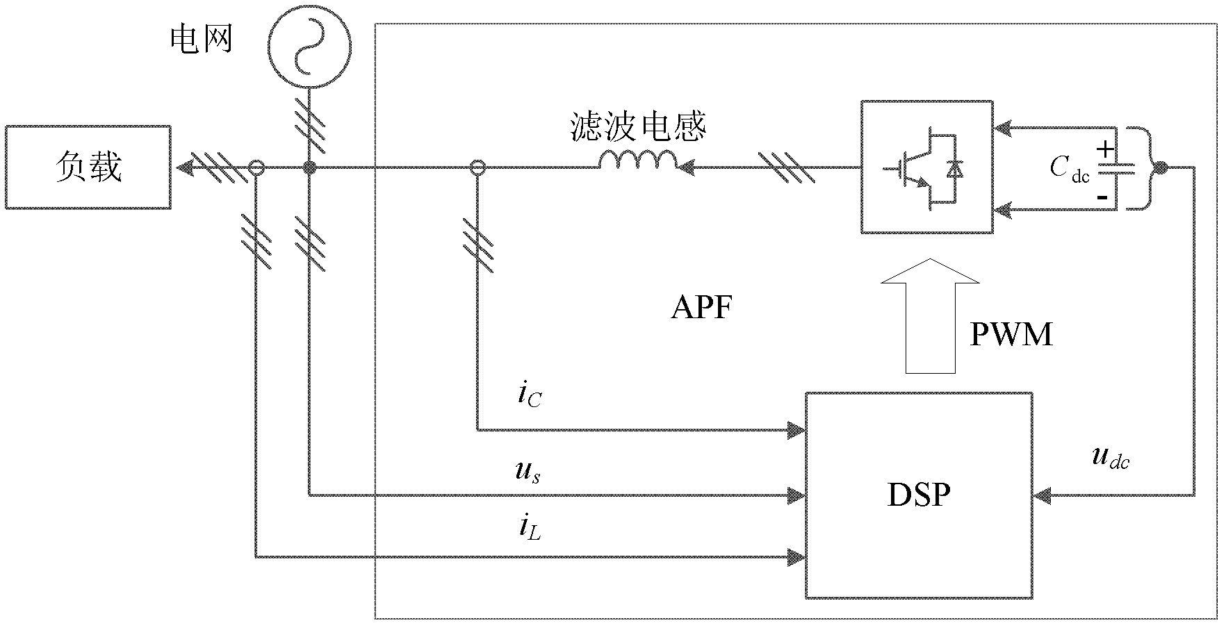
[0045] An APF used to inject compensation current into the grid, such as figure 1 As shown, it mainly includes two parts: the main circuit and the control system:

[0046]The main circuit is composed of a converter and a filter inductor. The grid side of the converter is connected to the grid through a filter inductor, and the DC side is connected in parallel with a DC support capacitor C dc ;

[0047] The control system is used to collect grid voltage u s , load current i L and the DC bus voltage u dc and compensation current i C , and construct PWM signals based on these signals to control the semiconductor devices in the APF converter; it consists of a DSP (digital signal processor, TI's TMS320F2812) and peripheral circuits such as some voltage and current sen...


PUM


Abstract

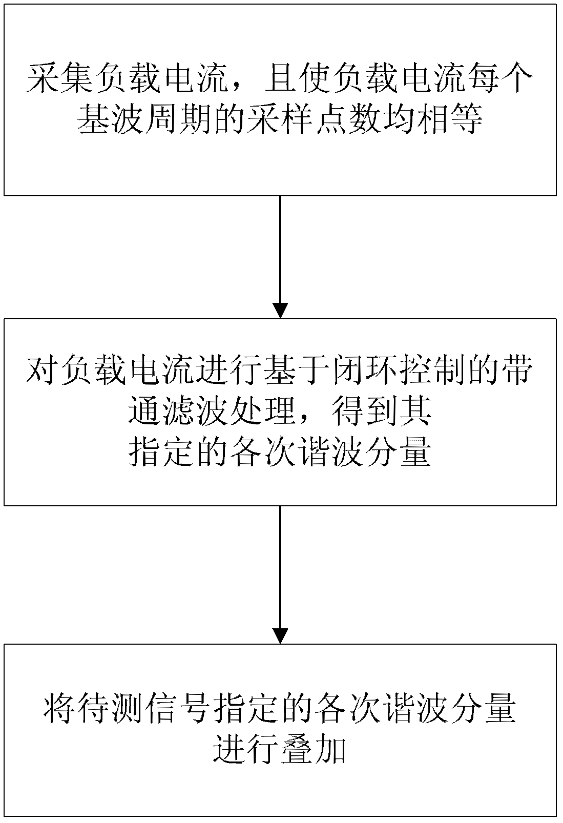
The invention discloses a selective harmonic wave extracting method, which comprises the following steps of: (1) acquiring load current, and keeping the quantities of sampling points at every fundamental wave period of the load current equal; (2) performing band-pass filtering processing on the load current based on closed-loop control to obtain each specified subharmonic component; and (3) overlapping each secondary harmonic component specified by a signal to be tested. By combining a phase-locked loop technology of a fixed point quantity, the selective harmonic wave extracting method with high performance is provided for a system which requires a fixed sampling point quantity; and under the condition of fluctuation of fundamental wave signal frequency, selective resonant wave extraction can be realized at high accuracy, occupied control system resources are reduced relatively, and high stable precision is achieved.

Description

technical field [0001] The invention belongs to the technical field of signal processing, and in particular relates to a selective harmonic extraction method. Background technique [0002] With the extensive use of power electronic devices and uncontrolled rectifier devices, the harmonics generated by them will cause increasingly serious pollution to the power grid. The fields involved in harmonic problems include: harmonic source analysis, power grid harmonic power flow calculation, harmonic compensation and transplantation technology, and harmonic measurement. [0003] Harmonic detection is an important branch of harmonic problems, which is of great significance to harmonic suppression and compensation, power system analysis and fault judgment. Accuracy and real-time performance are important criteria to measure the pros and cons of harmonic detection methods. Compared with the traditional full-bandwidth harmonic extraction method based on instantaneous reactive power th...

Claims


Application Information

Patent Timeline
IPC IPC(8): G01R23/16
Inventor 陈国柱贺超谢川闫辉
Owner ZHEJIANG UNIV
Learn More