
High-frequency non-inductive resistor

A technology of non-inductive resistors and resistors, applied in the direction of resistors, liquid resistors, resistor components, etc., can solve problems such as not being able to meet the on-load test and affecting the on-load measurement results of high-frequency equipment

Inactive Publication Date: 2012-08-01
HEBEI KAIXIANG ELECTRICAL TECH
View PDF1 Cites 1 Cited by
  • Summary
  • Abstract
  • Description
  • Claims
  • Application Information

AI Technical Summary

Problems solved by technology

[0002] For high-frequency circuits, the general load resistance itself has inductive reactance and capacitive reactance, not pure impedance, and is connected in series or parallel with distributed inductance and distributed capacitance, thus affecting the load measurement results of high-frequency equipment
[0003] At present, the power of dedicated high-frequency non-inductive resistors is less than 200W, and the maximum power reaches 1000W. Therefore, for high-power high-frequency equipment, such as transmitters above 50KW, the current low-power dedicated high-frequency non-inductive resistors cannot meet the requirements. its load test

Method used


Image

  • High-frequency non-inductive resistor
  • High-frequency non-inductive resistor

Examples


Embodiment Construction

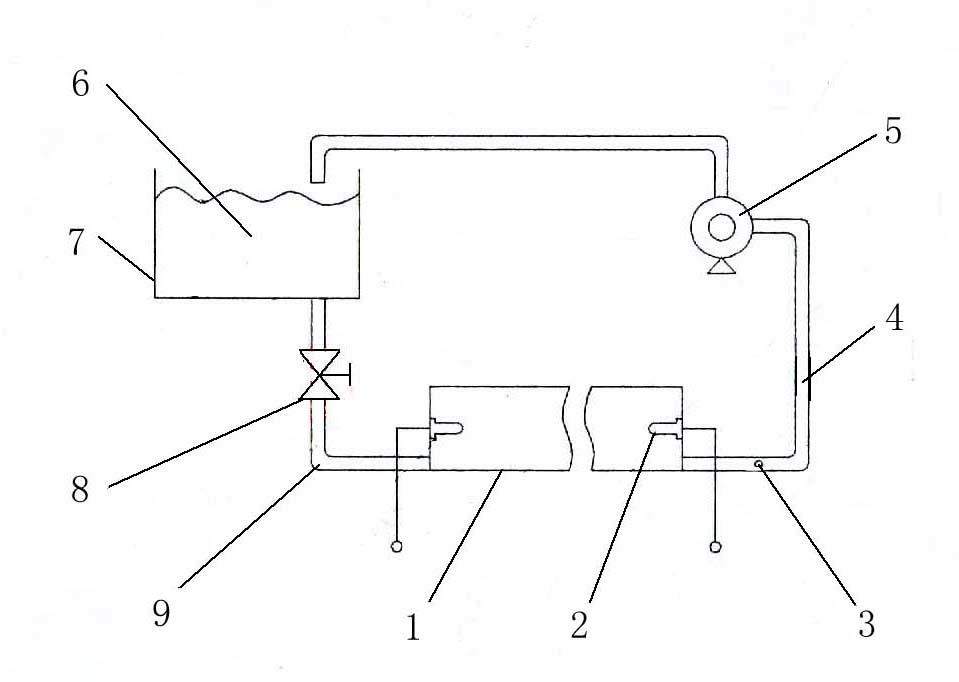
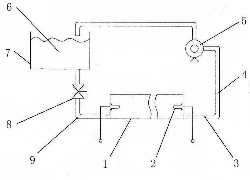
[0017] Depend on figure 1 It can be seen from the illustrated embodiment that it includes a resistor housing 1 containing brine, a columnar electrode 2 mounted on the left and right side walls of the resistor housing 1, a circulation pump 5, a water tank 7 containing brine, and a temperature sensor 3 The water tank 7 is located above the resistor housing 1, the water inlet on the left side wall of the resistor housing 1 communicates with the bottom of the water tank 7 through the water inlet pipe 9, and the right side of the resistor housing 1 The water outlet on the side wall communicates with the top of the water tank 7 through the water outlet pipe 4 equipped with the circulation pump 5, and the temperature sensor 3 is installed on the water outlet pipe at the water outlet on the right side wall of the resistor housing 1 4 on.

[0018] A valve 8 is installed on the water inlet pipe 9 .

[0019] The resistor housing 1 is tubular, and its material is insulating engineering ...


PUM


Abstract

The invention relates to a high-frequency non-inductive resistor, which comprises a resistor shell body, columnar electrodes, a circulating pump, a water tank and a temperature sensor, wherein the resistor shell body is used for containing saline water, and the columnar electrodes are arranged on the left and right side walls of the resistor shell body. The water tank is used for containing saline water and is positioned above the resistor shell body. A water inlet in the left side wall of the resistor shell body is communicated with the bottom of the water tank through a water inlet pipe, and a water outlet in the right side wall of the resistor shell body is communicated with the upper part of the water tank through a water outlet pipe provided with the circulating pump. The temperature sensor is installed on the water outlet pipe at the water outlet in the right side wall of the resistor shell body. The high-frequency non-inductive resistor has the following advantages that: (1) the high-frequency non-inductive resistor hardly generates distributed inductance and distributed capacitance, and is suitable for loading testing of high-frequency equipment with various powers; (2) and as the circulating pump is adopted to circulate and cool the saline water in the resistor shell body, the resistor is suitable for the loading testing of large-power high-frequency equipment, such as the loading testing of a transmitter of more than 50 kW (13MHz).

Description

technical field [0001] The invention relates to a high-frequency non-inductive resistor, which is suitable for on-load testing of high-frequency equipment. Background technique [0002] For high-frequency circuits, the general load resistance itself has inductive reactance and capacitive reactance, not pure impedance, and is connected in series or parallel with distributed inductance and distributed capacitance, thus affecting the load measurement results of high-frequency equipment. [0003] At present, the power of dedicated high-frequency non-inductive resistors is less than 200W, and the maximum power reaches 1000W. Therefore, for high-power high-frequency equipment, such as transmitters above 50KW, the current low-power dedicated high-frequency non-inductive resistors cannot meet the requirements. Its load test. Contents of the invention [0004] The technical problem to be solved by the present invention is to provide a high-frequency non-inductive resistor suitable...

Claims


Application Information

Patent Timeline
Patent Type & Authority Applications(China)
IPC IPC(8): H01C10/02H01C1/082
Inventor 李彦钢李宗蔚
Owner HEBEI KAIXIANG ELECTRICAL TECH
Learn More