


Quick Research
Generate reliable direction feasibility study reports for your R&D in just a few steps.

Technical Q&A
Discover and master advanced knowledge NOW. Basics, ideas, possibilities, all at once.

Find Solutions
As an expert in R&D theories, this can generate solutions to your technical problems instantly.

Evaluate Feasibility
Analyze your overall solution with one click, know your potential R&D risks in advance.

Monitor Landscape
Get weekly tech updates, stay abreast of the latest tech innovations and key insights.
Rubbing roller and manufacturing method thereof
A manufacturing method and rubbing roller technology, applied in optics, instruments, nonlinear optics, etc., can solve problems such as intrusion, liquid crystal display substrate quality degradation, etc., and achieve the effect of increasing the dangerous speed
- Summary
- Abstract
- Description
- Claims
- Application Information
AI Technical Summary
Problems solved by technology
Method used
Image

Examples
Embodiment 1
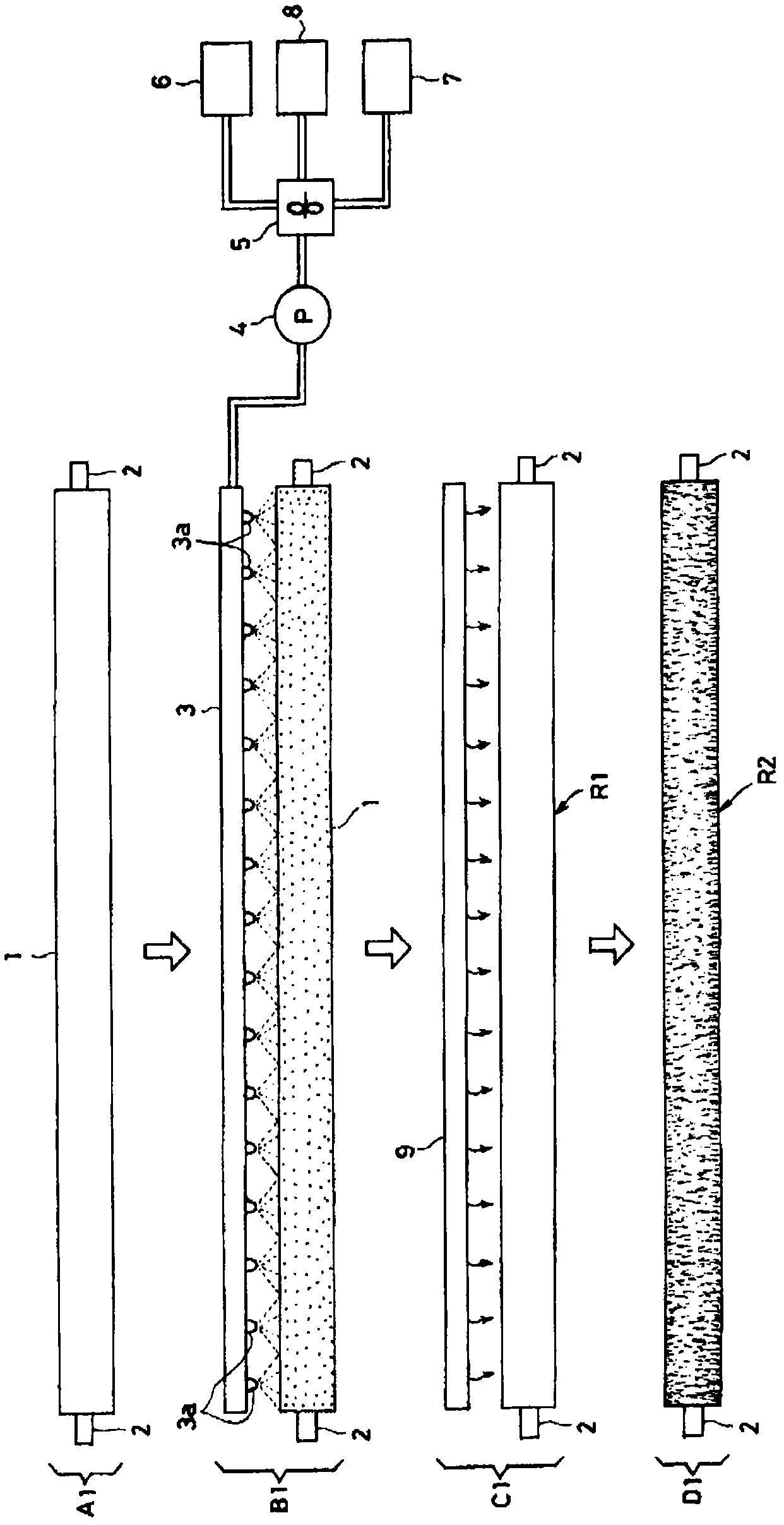
[0047] figure 1 It is a figure which shows the process of the manufacturing method of the friction roller of this invention which concerns on Example 1. As shown in this figure, in process A1, the metal rotating shaft is attached to both ends of CFRP1 which formed the hollow cylindrical shape with a predetermined diameter. Supports flange 2 and prepares for molding. Next, in step B1, above the CFRP 1, the spray device 3 in which a plurality of nozzles 3a are arranged in a row is disposed. The spraying device is connected to a pump 4 and then to a mixer 5 .
[0048]Taking epoxy resin as a thermosetting resin as an example, on the above-mentioned mixer 5, a main agent tank 6 storing the main agent and a curing agent tank 7 storing a curing agent which is mixed with the main agent to start curing are connected. , There is also a conductive material tank 8 for storing the conductive material mixed with the main agent and the curing agent.
[0049] The raw materials mentioned a...
Embodiment 2
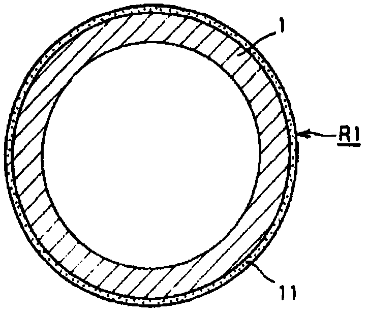
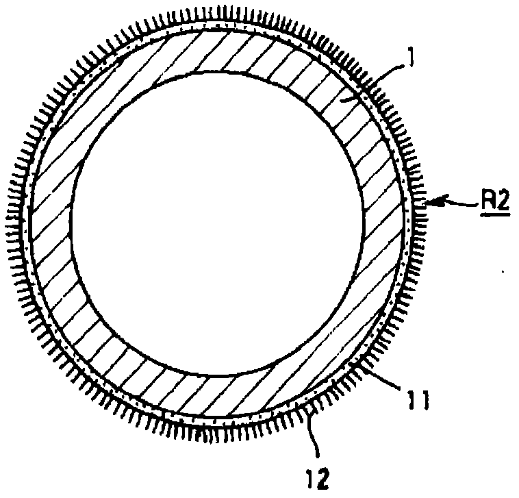
[0054] Figure 4 The process of the manufacturing method of the rubbing roller of this invention of Example 2 is shown, and the thicker conductive epoxy resin layer 11 is formed on the surface of CFRP1, and the member which can improve rigidity is formed. At the same time, the unevenness of the surface of CFRP 1 does not affect the conductive epoxy resin layer 11, and the conductive epoxy resin layer 11 has a smooth surface.
[0055] In the method of embodiment 2, utilize Figure 4 The process shown performs molding processing, and a molding cylinder 13 is used as shown in the figure. The molding cylinder 13 is a hollow cylindrical member made of high corrosion-resistant steel such as stainless steel, its two ends are open, and the inner peripheral surface is coated with, for example, polytetrafluoroethylene, that is, Teflon (registered trademark), to form a hollow cylinder. mold layer.
[0056] At the lower end of the above-mentioned molding cylinder 13, as Figure 5 A se...
PUM
 Abstract
Description
Claims
Application Information
 - R&D Engineer
- R&D Manager
- IP Professional
- Industry Leading Data Capabilities
- Powerful AI technology
- Patent DNA Extraction
Browse by: Latest US Patents, China's latest patents, Technical Efficacy Thesaurus, Application Domain, Technology Topic, Popular Technical Reports.
© 2024 PatSnap. All rights reserved.Legal|Privacy policy|Modern Slavery Act Transparency Statement|Sitemap|About US| Contact US: help@patsnap.com