
Current control method for three-phase rectifying device

A three-phase rectification and current control technology, which is applied in the output power conversion device, the conversion of AC power input to DC power output, electrical components and other directions, which can solve the current waveform distortion, low current control accuracy, and adjacent phase point disturbance. And other issues

Inactive Publication Date: 2012-07-25
UNIV OF ELECTRONIC SCI & TECH OF CHINA +1
View PDF2 Cites 8 Cited by
  • Summary
  • Abstract
  • Description
  • Claims
  • Application Information

AI Technical Summary

Problems solved by technology

The traditional PI control is to control the error between the reference quantity and the feedback quantity at adjacent phase points, but due to the influence of phase acquisition error and control delay, there will often be disturbances between adjacent phase points, so The traditional current control method is prone to the problems of low current control accuracy and current waveform distortion

Method used


Image

  • Current control method for three-phase rectifying device
  • Current control method for three-phase rectifying device
  • Current control method for three-phase rectifying device

Examples


example

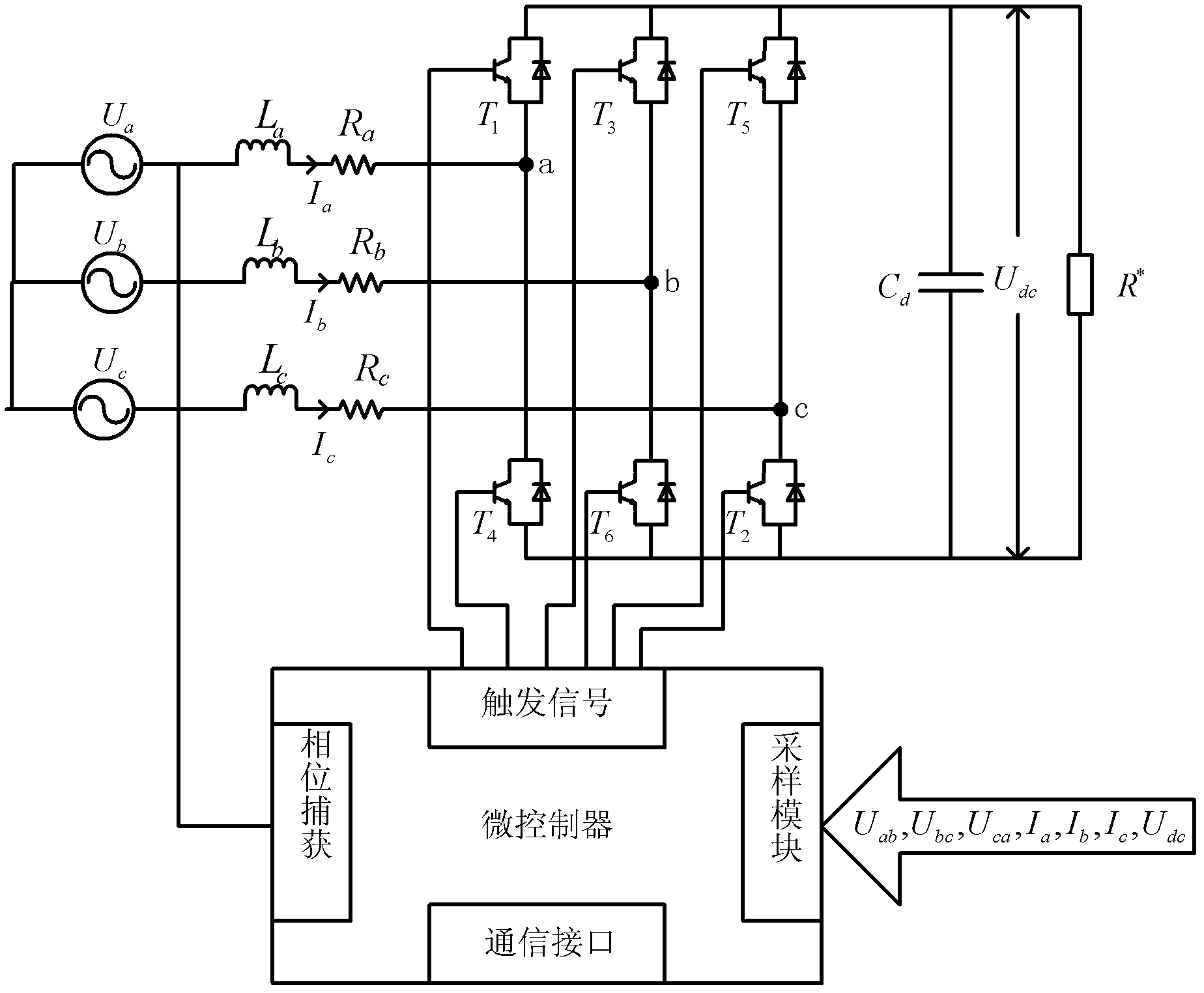
[0066] Using the current control method of the invented three-phase rectifier, using TI's TMS320F2812 as the controller, the input voltage and current waveform of the grid side is as follows Figure 4 As shown, its upper half is the voltage U i (i=a, b, c) waveform, the lower part is the current I i (i=a, b, c) waveform. Using the development environment CCStudiov3.3 provided by TI, it is obtained by sampling the voltage and current at the same time, and the sampling frequency is 9KHz. from Figure 4 It can be seen that the grid side input current I i Well tracked grid voltage U i, which maximizes the system power factor and reduces the harmonic content.


PUM


Abstract

The invention provides a current control method for a three-phase rectifying device in order to solve the problems of low current precision control and current waveform distortions in the prior art and modify a PI (potential intensity) controller to subject each phase point of grid current to PI adjustment. An attenuation coefficient K is used for attenuation of error values to enable previous accumulated errors to be attenuated along with time. According to a test that the magnitude of errors nearby the current grid cycle plays a leading role and current electric current can better track expected current, the current control method has the advantages that defects in the traditional methods can be effectively overcome, current control precision is improved, and the power factor of the three-phase rectifying device can be further improved while harmonic component is reduced.

Description

technical field [0001] The invention belongs to the technical field of power supplies, and more specifically relates to a current control method of a three-phase rectifier realized based on IGBT semiconductor switching elements. Background technique [0002] In an ideal power system, the grid voltage and current should be sinusoidal at power frequency. With the rapid development of power electronics technology, various rectification devices based on pulse width modulation (PWM) control, such as high-frequency switching power supply, inverter power supply, frequency converter, etc., have been widely used in various fields of national economy. And these rectifiers become the nonlinear load of the power grid, generating a large amount of harmonic current. Therefore, in the actual operation of the power system, even if the voltage of the rectifier device in the power system is a sine wave, due to the influence of nonlinear loads, the lines in the power system and at the user wi...

Claims


Application Information

Patent Timeline
IPC IPC(8): H02M7/219
Inventor 程玉华顾永德黄建国白利兵陈凯聂琳
Owner UNIV OF ELECTRONIC SCI & TECH OF CHINA
Learn More