Vacuum test device for testing induction motor stator performance

A testing device and induction motor technology, applied in the direction of motor generator testing, etc., can solve the problems of high maintenance cost, uneven force on the guide rail, and low service life, so as to reduce the failure rate and maintenance cost, and avoid the bending of the guide rail. Folding inclination, the effect of increasing the service life

Active Publication Date: 2015-02-18
合肥凯邦电机有限公司
View PDF5 Cites 0 Cited by
  • Summary
  • Abstract
  • Description
  • Claims
  • Application Information

AI Technical Summary

Problems solved by technology

The above-mentioned structure has the following defects: on the one hand, during vacuum extraction, the cover body of the vacuum cover shrinks and drives the end of the cantilever rod to produce a downward movement, and at the same time, the vacuum cover itself will also exert pressure on the cantilever rod when it is suspended. The mounting plate fixed to it is tilted, which leads to uneven force on the guide rail, which affects the normal operation of the device. At the same time, after the mounting plate is tilted, it is easy to cause the screws on the mounting plate to break phenomenon, the experiment had to be interrupted for maintenance and replacement. All of the above have led to a high failure rate and a low service life of the vacuum test device for the performance test of the induction motor stator. At the same time, its maintenance cost is also extremely high; The radial dimension of the gasket ring opening is consistent with the radial dimension of the vacuum cover opening, which often affects the actual sealing state of the vacuum cover in the suspended state when it falls in actual operation, and ultimately affects the accuracy of its experimental data

Method used


Image

  • Vacuum test device for testing induction motor stator performance
  • Vacuum test device for testing induction motor stator performance
  • Vacuum test device for testing induction motor stator performance

Examples


Embodiment Construction

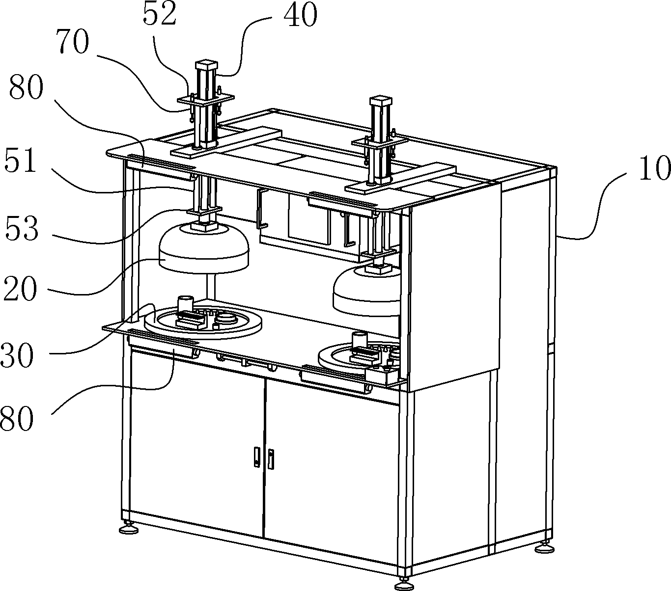
[0010] A vacuum test device for the performance of the stator of an induction motor, comprising a workbench 10 and a vacuum cover 20 suspended above the table of the workbench 10, and a sealing assembly matching the mouth of the vacuum cover 20 is arranged on the table 30. The vacuum test device also includes a vacuum pumping component a and an induction motor stator test component b, the fixed test end of the induction motor stator test component is located in the area enclosed by the sealing component 30, and the workbench 10 It is also provided with a power source 40 for driving the vacuum cover 20 to reciprocate linearly up and down and a guide part guiding the action direction of the vacuum cover 20. The guide parts are more than two and arranged symmetrically on both sides of the vacuum cover 20 cover axis. like Figure 1-4 shown.

[0011] As a further preferred version of the present invention: as Figure 4 As shown, the power source 40 is a piston cylinder, the top e...


PUM


Abstract

The invention belongs to the field of the application of a motor detection technology, and specifically relates to a vacuum test device for testing the induction motor stator performance. The vacuum test device provided by the invention comprises a working table frame and a vacuum cover suspended above the tabletop of the working table frame; a sealing component matched with a vacuum cover opening is correspondingly arranged on the tabletop; the vacuum test device also comprises a vacuumizing component and an induction motor stator test component; a fixed test end of the induction motor stator test component is located in an area surrounded by the sealing component; the working table frame is also provided with a power source for driving the vacuum cover to linearly reciprocate up and down and guide parts for guiding the moving direction of the vacuum cover; and more than two guide parts are provided and symmetrically arranged on the two sides of the axis of the vacuum cover body. In the invention, since the guide structures are symmetrically arranged on the two sides of the axis of the vacuum cover, the vacuum cover, the guide parts and even the whole structure experience balanced and uniform stress in movement, thus the fault rate and maintenance cost are greatly reduced, the working reliability is high, and the service life is obviously prolonged.

Description

technical field [0001] The invention belongs to the application field of motor detection technology, and in particular relates to a vacuum test device for testing the performance of an induction motor stator. Background technique [0002] At present, vacuum testing devices used for performance testing of induction motor stators generally use a cantilever structure, specifically including a vertically arranged guide rail part, and a horizontal mounting plate is arranged on the guide rail part, and the horizontal mounting plate is arranged parallel to the direction of one side of the board surface. There is a cantilever rod, and the top of the cantilever rod is suspended with a vacuum cover, and a workbench for arranging various measuring units is arranged directly under the vacuum cover to form a sealing fit with it, and the mounting plate is driven by the cylinder to reciprocate up and down along the guide rail. Linear motion; in actual work, fix the probe to be measured on ...

Claims


Application Information

Patent Timeline
Patent Type & Authority Patents(China)
IPC IPC(8): G01R31/34
Inventor 汪守峰韦青松张小军郑志鹏杨应建曾志敏
Owner 合肥凯邦电机有限公司
Why Eureka
Try Eureka