
Switched reluctance type gearless tractor

A technology of gear traction machine and switched reluctance, which is applied to elevators, transportation and packaging in buildings, etc., can solve the problem of reducing the reliability of permanent magnet synchronous traction machine, limiting the development of permanent magnet synchronous traction machine, traction The complex structure of the machine can achieve the effect of compact structure, low noise and small volume.

Inactive Publication Date: 2012-07-25
浙江西子富沃德电机有限公司
View PDF8 Cites 7 Cited by
  • Summary
  • Abstract
  • Description
  • Claims
  • Application Information

AI Technical Summary

Problems solved by technology

[0002] Traditional elevator traction machines generally use three-phase asynchronous motors, which are large in size, loud in noise and low in efficiency; in addition, they must be equipped with complex structure reduction gears to work together, making the structure of the entire traction machine complex and the cost of the whole machine Improvement, high failure rate, and relatively high maintenance costs
In recent years, the permanent magnet synchronous traction machine has developed rapidly, and there is a tendency to replace the traditional traction machine using three-phase asynchronous motors. However, with the rapid increase in the price of rare earth materials, the cost of the entire traction machine has doubled, and the high cost has greatly limited The development of permanent magnet synchronous traction machine; and the permanent magnet is easy to demagnetize at high temperature, if the design is not proper, the reliability of the permanent magnet synchronous traction machine will be greatly reduced

Method used


Image

  • Switched reluctance type gearless tractor
  • Switched reluctance type gearless tractor
  • Switched reluctance type gearless tractor

Examples


Embodiment Construction

[0017] In order to make the object, technical solution and beneficial technical effect of the present invention clearer, the technical content and specific implementation methods of the present invention will be further described in detail below in conjunction with the accompanying drawings. It should be understood that the specific implementations described in this specification are only for explaining the present invention, not for limiting the present invention.

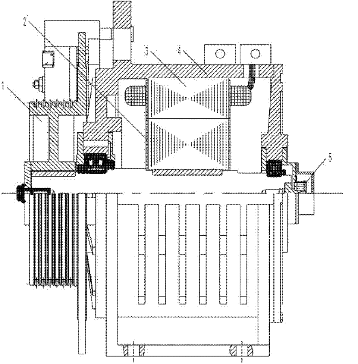
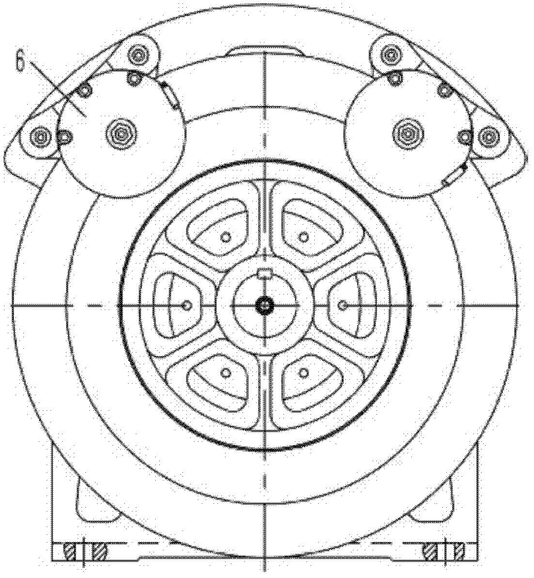
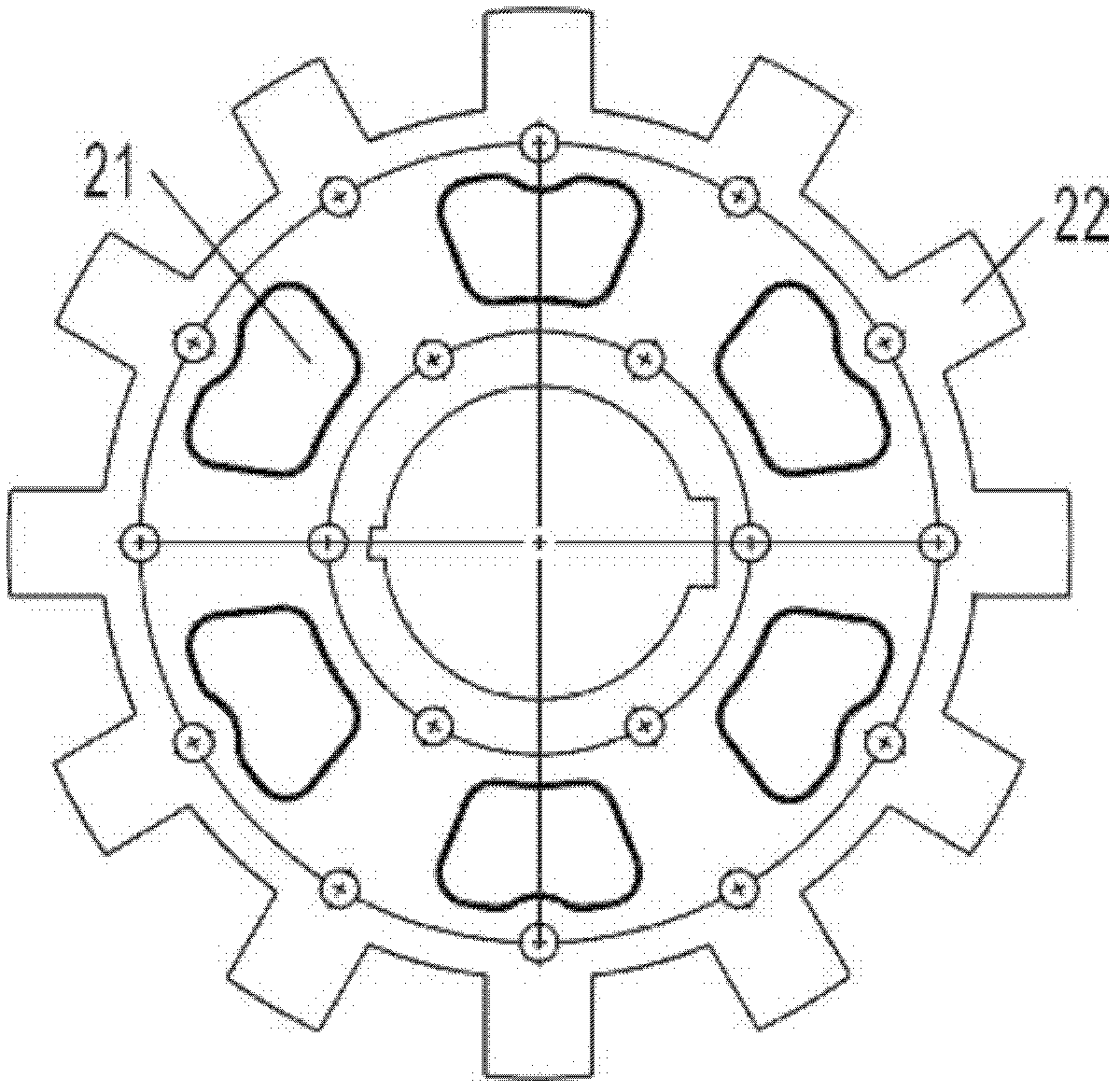
[0018] refer to Figure 1 to Figure 3 As shown, the switched reluctance gearless traction machine of the present invention includes a switched reluctance motor, a traction wheel 1, a sensor 5 and a brake 6, wherein the switched reluctance motor includes a base 4, a rotor 2 and a stator 3, and the switched reluctance motor The resistance motor drives the traction sheave 1 to rotate to provide traction driving force for the elevator running, and the rotor 2 and the stator 3 are installed on the machine base 4 . The...


PUM


Abstract

The invention provides a switched reluctance type gearless tractor, which comprises an electric motor, a traction wheel, a sensor and at least two brakes, wherein the electric motor is a switched reluctance motor; the switched reluctance motor comprises an engine base, a rotor and a stator; the switched reluctance motor drives the traction wheel to rotate to provide a traction driving force for the running of an elevator; the rotor and the stator are installed on the engine base; the sensor is installed inside the engine base; a controller controls on-off of each phase winding of the stator according to a certain rule and position information of the rotor detected by the sensor to produce the electromagnetic torque to drive the rotor to rotate, so as to produce the driving force; and the brakes are installed on two sides of the engine base. The tractor of the invention adopts the switched reluctance motor to drive the traction wheel to rotate, and the rotor is formed by the overlapping of a rotating shaft and a salient pole silicon steel sheet. In comparison with the prior art, the tractor of the invention greatly simplifies the structure of the tractor, greatly reduces the cost of a complete machine, and is compact in structure and small in volume.

Description

technical field [0001] The invention belongs to the technical field of elevator drive, in particular to a switched reluctance type gearless traction machine. Background technique [0002] Traditional elevator traction machines generally use three-phase asynchronous motors, which are large in size, loud in noise and low in efficiency; in addition, they must be equipped with complex structure reduction gears to work together, making the structure of the entire traction machine complex and the cost of the whole machine Improvement, high failure rate, and relatively high maintenance costs. In recent years, the permanent magnet synchronous traction machine has developed rapidly, and there is a tendency to replace the traditional traction machine using three-phase asynchronous motors. However, with the rapid increase in the price of rare earth materials, the cost of the entire traction machine has doubled, and the high cost has greatly limited The development of permanent magnet ...

Claims


Application Information

Patent Timeline
Patent Type & Authority Applications(China)
IPC IPC(8): B66B11/04
Inventor 林云发李创平罗昊郑啸
Owner 浙江西子富沃德电机有限公司
Learn More