Yarn winding machine

A yarn winding machine and yarn technology, applied in the direction of conveying filamentous materials, thin material handling, transportation and packaging, etc., can solve the problems that the yarn can not be pushed out, there is no record guide frame, etc.

Active Publication Date: 2012-07-25
MURATA MASCH LTD
View PDF7 Cites 16 Cited by
  • Summary
  • Abstract
  • Description
  • Claims
  • Application Information

AI Technical Summary

Problems solved by technology

[0005] Regarding this point, in Japanese Patent Application Laid-Open No. 2006-298499, although a guide frame is disclosed, the purpose of setting the guide frame is not described.
In addition, in the configuration of the guide frame, it is also impossible to prevent the yarn from being pushed out by the yarn guide.

Method used


Image

  • Yarn winding machine
  • Yarn winding machine
  • Yarn winding machine

Examples


Embodiment Construction

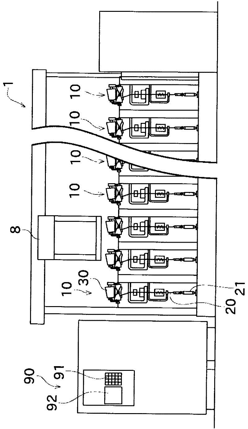
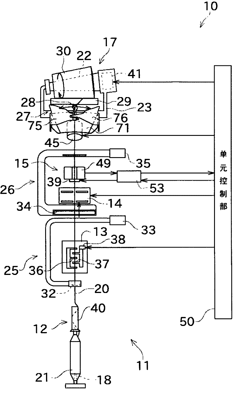
[0037] Next, embodiments of the invention will be described. First, refer to figure 1 The overall configuration of the automatic winder 1 of this embodiment will be described. figure 1 It is a front view of the automatic winder 1 according to one embodiment of the present invention. In addition, in this specification, "upstream" and "downstream" mean upstream and downstream in the moving direction of the yarn at the time of yarn winding. That is, if figure 2 etc., in this embodiment, the yarn 20 unwound from the yarn supplying bobbin 21 in the bobbin setting part 18 is wound by the winding part 17, so the bobbin setting part 18 side becomes upstream, and the winding part 17 side become downstream.

[0038] Such as figure 1 As shown, an automatic winder (yarn winder) 1 is mainly composed of a plurality of winder units (winder units) 10 arranged in parallel, an automatic doffing device 8, and a machine control device. (machine control device)90.

[0039] Each winder unit...


PUM


Abstract

An automatic winder includes a bobbin set section, a cradle (23), a contact roller (29), a traverse guide (28), and a yarn leading plate (75, 76). The bobbin set section supplies a yarn of a yarn supplying bobbin. The cradle (23) rotatably holds a package (30), around which the yarn (20) supplied from the bobbin set section is wound. The contact roller (29) makes contact with and rotates the package (30). The traverse guide (28) is provided independently from the contact roller (29). The traverse guide (28) is engaged with the yarn (20) to be wound into the package (30) to traverse the yarn (20). The yarn leading plate (75, 76) makes contact with the yarn (20) applied with tension to lead the yarn (20) towards a center in a winding width direction of the package (30) before the traverse guide (28) engages with the yarn (20).

Description

technical field [0001] The present invention relates to a yarn winding machine which supplies yarn from a yarn supply unit and winds it into a package while traversing. Background technique [0002] For example, Japanese Patent Application Laid-Open No. 2006-298499 discloses such a yarn winding machine. The yarn winding machine disclosed in Japanese Patent Application Laid-Open No. 2006-298499 includes a yarn guide shuttle for reciprocatingly guiding the yarn. This guide shuttle includes an arm attached to a rotating shaft of a drive device, and a yarn guide (traversing yarn guide) attached to a front end portion of the arm. The yarn guide at the tip of the yarn guide shuttle reciprocates while drawing an arc-shaped trajectory by the forward and reverse rotation of the rotating shaft of the driving device. The yarn winding machine disclosed in Japanese Unexamined Patent Application Publication No. 2006-298499 includes a gate-shaped guide frame arranged along a rail at the ...

Claims


Application Information

Patent Timeline
IPC IPC(8): B65H54/28
CPCB65H2701/31B65H57/02B65H54/2827
Inventor 木野义浩
Owner MURATA MASCH LTD
Why Eureka
Try Eureka