Laser processing device

A laser processing device, laser technology, applied in printing devices, laser welding equipment, printing and other directions, can solve the problem of laser leakage head shell and other problems

Inactive Publication Date: 2012-07-25
KEYENCE
View PDF1 Cites 2 Cited by
  • Summary
  • Abstract
  • Description
  • Claims
  • Application Information

AI Technical Summary

Problems solved by technology

However, if this structure is adopted, the laser light may be emitted from the camera opening as return light from the workpiece or scattered light from the optical system
For example, if the camera is detached during laser irradiation or if laser irradiation is performed without the camera attached, laser light may leak to the outside of the head case

Method used


Image

  • Laser processing device
  • Laser processing device
  • Laser processing device

Examples


Embodiment Construction

[0044]

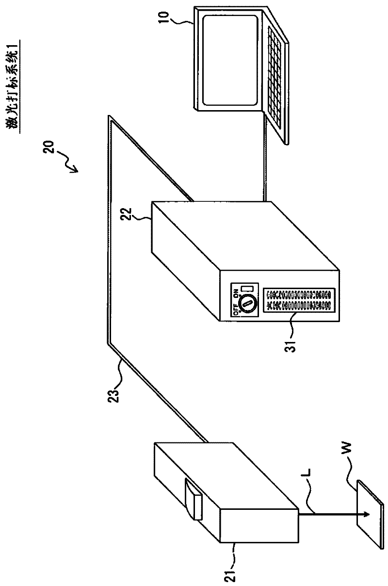
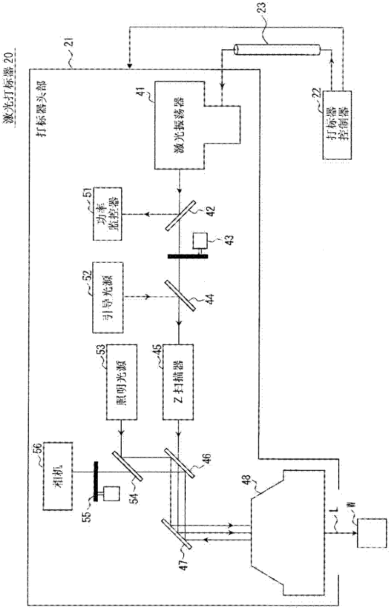
[0045] figure 1 is a system diagram showing one example of a schematic configuration of a laser marking system 1 including a laser processing apparatus according to an embodiment of the present invention, in which a laser marker 20 is shown as an example of the laser processing apparatus. The laser marking system 1 is configured by a laser marker 20 for processing a workpiece W by applying laser light L, and a terminal device 10 for editing processing conditions. The laser marker 20 includes a marker head 21 for generating and scanning laser light L, and a marker controller 22 for performing operation control of the marker head 21 .

[0046] The terminal device 10 is a device for controlling the laser marker 20, for example, it may be a personal computer installed with a laser marker application program. The user uses the terminal device 10 to create and edit processing setting data defining processing conditions of the laser marker 20 . The marker controller 22 p...


PUM


Abstract

Provided is a laser processing device capable of preventing laser light from leaking out to the outside of the housing by emitting the laser light to the processing target with the camera detached. The laser processing device includes a laser generator; a scanning optical system for scanning the laser light with respect to a workpiece; a housing frame for accommodating the scanning optical system; a camera for photographing the workpiece, the camera being removably attached to the housing frame and having a light receiving axis branched from an emission axis of the laser light; a camera cover removably attached to the housing frame to cover the camera; a limit SW for detecting detachment of the camera cover from the housing frame; and a laser output control section for prohibiting the emission of the laser light to the workpiece based on a cover detection signal.

Description

technical field [0001] The present invention relates to a laser processing device, and more particularly, to an improvement of a laser processing device for processing a processing object by applying laser light. Background technique [0002] The laser marking device is a laser processing device that processes the processing object (workpiece) by applying laser light and can print characters, marks, graphics, etc. on the workpiece by scanning the irradiation position of the laser light. Among such laser marking devices, there is known a device in which a workpiece is photographed by a camera, and inspection and adjustment of a processing position are performed (for example, Japanese Unexamined Patent Publication No. 2009-78280). [0003] The laser marking device described in Japanese Unexamined Patent Publication No. 2009-78280 incorporates a camera for taking pictures of the workpiece in the head housing, and the laser marking device is configured by aligning the light-rece...

Claims


Application Information

Patent Timeline
Patent Type & Authority Applications(China)
IPC IPC(8): B41J2/45B41J29/38B23K26/00
CPCB23K26/0807B41M5/24B23K26/0084B41J2/442B23K26/032B23K26/00B23K26/082B23K26/355
Inventor 洼田诚
Owner KEYENCE
Why Eureka
Try Eureka