
Ethernet power supply sensor network

A technology of sensor network and sensor network of the power supply, which is applied in the field of Ethernet data transmission in the Internet of Things, and can solve problems such as complex wiring

Inactive Publication Date: 2012-07-18
SHANGHAI DAIHEYI INFO TECH
View PDF0 Cites 10 Cited by
  • Summary
  • Abstract
  • Description
  • Claims
  • Application Information

AI Technical Summary

Problems solved by technology

[0004] In order to solve the problem of complex wiring in wired data transmission in the Internet of Things and ensure the reliability of data transmission at the same time, the present invention provides an Ethernet chain or ring data transmission with simple wiring, high reliability, and less susceptible to external interference Network, which is applied to the chain and ring power supply structure of Ethernet power transmission, the name is Power over Ethernet sensor network, the power supply over Ethernet sensor network is a chain structure or ring structure, and the chain structure includes a main power supply A chain data communication structure formed by connecting equipment and multiple powered equipments in series with Ethernet; ring structure includes a ring data communication structure formed by connecting a main power supply equipment and multiple powered equipments in series with Ethernet; the power supply adopts Ethernet power supply mode, data transmission and power supply use the same Ethernet cable

Method used


Image

  • Ethernet power supply sensor network
  • Ethernet power supply sensor network
  • Ethernet power supply sensor network

Examples


Embodiment Construction

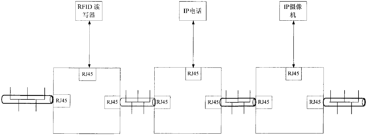
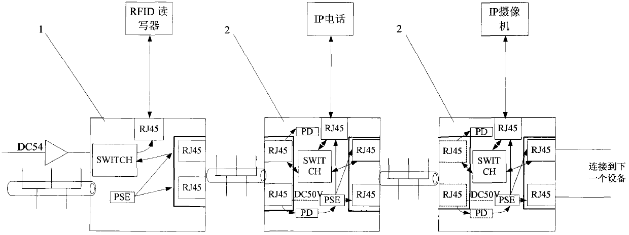
[0011] For such as figure 1 figure 2 image 3 The power-over-Ethernet chain sensor network shown in detail is as follows:

[0012] (1) if figure 1 as shown in figure 1 It is an explanatory diagram of the data transmission of the Ethernet-powered chain sensor network, and its data transmission is basically the same as that of the normal Ethernet transmission; figure 2 It is an explanatory diagram of the power transmission of the ether-powered chain sensor network. The RJ45 connecting the main power supply device 1 and the powered device 2, or connecting two powered devices 2 has 8 wires, of which 1236 is a group. 4578 for a group. When the transmission rate is 10M or 100M, 1236 is used to transmit data, and 4578 is idle. At this time, 1236 can be used to transmit power. The 8-pin connection is the negative pole, but the above two methods cannot be used to transmit power at the same time, only one of them can be used, and which group is used to transmit power is set by t...


PUM


Abstract

The invention relates to the field of Ethernet data transmission. The invention relates to an Ethernet power supply sensor network and provides an Ethernet chain-shaped or ring-shaped data transmission network which is simple in wiring and high in reliability, is not interfered by outside, and is applied to chain-shaped and ring-shaped power supply structures of Ethernet power transmission. The Ethernet power supply sensor network is in a chain-shaped or ring-shaped structure, wherein the chain-shaped comprises primary power supply equipment and a plurality of powered equipment which are connected by the Ethernet in series to form a chain-shaped data communication structure; the ring-shaped structure comprises primary power supply equipment and a plurality of powered equipment which are connected by the Ethernet in series to form a ring-shaped data communication structure; and the power supply utilizes an Ethernet power supply way, and the data transmission and the power supply utilize the same Ethernet wire. The Ethernet power supply sensor network disclosed by the invention has the advantages that the power supply and the data transmission share the same transmission wire. The wiring is convenient and the wiring cost is saved.

Description

technical field [0001] The invention relates to the field of Ethernet data transmission in the internet of things. Background technique [0002] At present, data transmission in the Internet of Things includes wired data communication and wireless data communication. Due to the wide variety of fieldbuses in wired communication technology, there is a huge amount of deployment, and data collection in the Internet of Things generally distributes many and wide collection points, but the data The amount is not very large. If conventional wiring is used, wiring is often difficult and costly, and resources are seriously wasted. However, if wireless communication is used, the reliability is poor, and it is easy to be interfered by the outside world, which has a great impact on the safe transmission of data. [0003] Ethernet applications are mainly point-to-point or tree-shaped applications at present, but this connection method has no protection function for data transmission, and...

Claims


Application Information

Patent Timeline
Patent Type & Authority Applications(China)
IPC IPC(8): H04L12/10H04L12/28
Inventor 廖毅文
Owner SHANGHAI DAIHEYI INFO TECH
Learn More